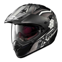
This document is a user manual for the X-lite X-551 helmet, providing instructions for its safe use, maintenance, and various features.
Function Description:
The X-lite X-551 helmet is a high-performance helmet designed for motorcycle and motorbike use. Its primary function is to provide protection to the head in the event of an accident, limiting injuries and damage. The helmet incorporates advanced design elements focusing on ergonomics, comfort, aerodynamics, and user-friendly controls to meet high standards of safety and comfort. It features a Vision Protection System (VPS) as an internal sunscreen, a scratch-resistant racing visor, and various ventilation systems to enhance the rider's experience in different conditions.
Important Technical Specifications:
- Visor: Scratch-resistant racing visor, convex coated LEXAN® with uniform thickness.
- Internal Sunscreen (VPS): LEXAN®-moulded, anti-scratch treated.
- Retention System: Standard length strap, factory-adjusted.
- Inner Visor (NFRS - Nolan Fog Resistant System): Available as standard or optional accessory.
- Ventilation Systems:
- Front Ventilation System (Fig. 18): Air intake in the front part of the shell, maximum efficiency when VPS is active (lowered).
- Top Ventilation System (Fig. 19): Two upper air intakes for air circulation, independent of VPS position.
- Rear Extractor (Fig. 20): Ensures optimal heat dissipation.
- Lower Ventilation System (Fig. 21): Chin guard ventilation controlled by two flaps.
- Internal Components: Inner comfort padding and cheek pads. Polystyrene internal components designed to absorb impacts through deformation or partial destruction.
- Approval Standards: Complies with ECE22-05, requiring minimum light transmittance levels for visors (greater than 80% at night, not less than 50% during the day).
- Manufacturing: Produced in an establishment that respects the environment.
Usage Features:
Helmet Selection and Fit:
- Size: To determine the correct size, try on different helmets and choose one that fits the head shape best, feels firm when worn and fastened, and provides good comfort. A helmet that is too large may slide down, covering the eyes or turning sideways while riding.
- Pressure Points: Wear the helmet for a few minutes to ensure there are no extreme pressure points that could cause pain or headache.
- Taking Off: With the helmet on and the strap securely fastened, attempt to take it off as shown in Fig. A. This checks if the helmet could slip off in an accident due to various forces. The helmet should not rotate, move freely, or slip off the head. If it does, adjust the strap length or change the helmet size and repeat the test.
Retention System:
- Adjustment: The strap is factory-adjusted to a standard length. Before use, ensure correct pre-adjustment.
- Security: The strap must always be securely fastened and tightened to keep the helmet firm on the head. Before riding, ensure the strap is well-fastened under the chin, as far back towards the throat as possible, without being uncomfortable.
- Tension: Correct strap tension should allow normal breathing and swallowing, but prevent a finger from passing between the strap and the throat.
- Button (if present): The button on the strap only prevents the end of the strap from flapping once it has been correctly fastened.
Peak (Visor):
- Adjustment (Fig. 1, 2): For road use, the peak must be adjusted to the highest position. Release upper latch A and side latches B by unscrewing them anticlockwise. Adjust the peak height to the desired position (highest for road use). Lock the peak by tightening latch A and side latches B clockwise.
- Disassembly: To remove the peak completely, unscrew latch A and side latches B anticlockwise.
- Assembly: Place the peak on the shell, ensuring latches A and B are inserted into their slots. Lock latches B clockwise to their original position. Adjust the peak as described above.
- Note: The peak must be removed to disassemble the main visor. If using the helmet without the peak (Fig. 17), insert the stoppers as shown in Fig. 3.
Main Visor (Scratch Resistant Racing Visor):
- Disassembly (Fig. 4): Open the visor completely. Press and hold the visor release button (A) and slide the visor forward until it clicks. Free the visor fastenings (B1 and B2) from their housing. Repeat on the other side.
- Assembly (Fig. 5): Set the visor in the open position, aligning fastenings (B1 and B2) with the housings in the visor mechanism. Insert fastening B1, press the visor against the shell at fastening B2 to activate the release button. Slide the visor until it locks. Repeat on the other side.
- Adjustment (Fig. 6): The visor mechanism has a clearance adjustment system to ensure effective sealing against the visor trim. The mechanism support has upper and lower reference teeth. The helmet is supplied with the correct adjustment. Periodically check that the closed visor adheres uniformly and symmetrically to the deformable lip of the trim. If not, disassemble the visor, check the mechanism's position (A1, A2), loosen screws B1 and B2 (2.5 mm Allen wrench), lift and move the mechanism forward or backward, then lower it so A1 and A2 teeth engage in the same position. Tighten screws B1 and B2. Repeat on the other side. Reassemble the visor and check adherence.
- Warning: After any assembly/disassembly, check the visor mechanism's correct function. Do not remove the visor opening/closing mechanisms from the shell.
Wind Protector (Fig. 7):
- This accessory improves helmet performance by preventing uncomfortable air infiltration under the chin. Refer to Fig. 7 for assembly and disassembly.
Inner Comfort Padding (Racing Comfort):
- To remove/reassemble the inner comfort padding, lift the VPS (Fig. 12A).
Cheek Pads:
- Disassembly (Fig. 8A, 8B): Open the chin strap. Pull the front part of the left cheek pad padding inwards to release the 4 snap fasteners on its back. Remove the padding by pulling the left chin strap out of its slot. Repeat for the right cheek pad. It is not necessary to remove the polystyrene foam cheek pads with the snap fastener holes.
- Fitting: Insert the chin strap band and left chin strap into the slot of the left cheek pad. Place the left cheek pad against the polystyrene inner cheek pad, fastening the lower buttons into the roll-neck eyelet and pushing the padding near the 4 snap fasteners to their seats. Repeat for the right cheek pad.
- Warning: Remove padding only for cleaning/washing. Never use the helmet if padding is not correctly restored.
Liner:
- Removal (Fig. 9, 10, 11): Release the roll neck flap between the EPS cheek pad and outer shell. Unhook the rear left fastening flap from the inner shell support and pull the comfort padding gently inwards at the neck-ring area. Repeat for central and right rear flaps. Hold the left front part of the liner and pull it upwards to remove the liner flap from the polystyrene inner shell support. Repeat for right and central front flaps. Completely remove the liner.
- Assembly: Insert the liner correctly and fit it well. Insert the left front flap into its seat on the polystyrene inner shell support and push it down until locked. Repeat for right and central front flaps. Insert rear right, central, and left flaps into their support seats in the neck-ring area and push until fully hooked. Insert the roll neck flap between the EPS cheek pad and outer shell. Adjust the liner until it adheres well.
- Note: Check correct assembly of the liner front area by lifting and lowering the VPS; movements should be smooth. If not, repeat steps 1.3 and 2.2.
Vision Protection System (VPS):
- Function (Fig. 12A, 12B): The VPS is an internal sunscreen that can be lowered to partially cover the visor field of vision, reducing light transmittance. It can be deactivated by pushing the slider towards the back (Fig. 12A) until a click is heard, or activated by pushing the slider forward (Fig. 12B).
- Disassembly (Fig. 12C, 13): Open the helmet visor and lower the VPS by pushing the side slider all the way forward to the second click. Hold the left part of the VPS and pull it downward until its grip pawl is removed from the mechanism. Repeat on the right side and remove.
- Assembly: Open the helmet visor and ensure the side slider is in the forward position. Insert the left end of the VPS into the left side guide until the grip pawl hooks into the mechanism. Repeat on the right side. Check VPS function by moving the slider forward and backward, listening for clicks.
- Precautions:
- Activate/deactivate VPS only with the slider; do not manipulate it directly.
- Use VPS only during the day and in described environmental conditions.
- VPS MUST be deactivated at night or in poor visibility.
- Always check VPS positioning for weather/environmental conditions.
- Recommended for use only with the approved standard visor (transmittance > 80%).
- VPS does not replace visor protection.
- Ensure VPS is clean and functional to avoid scratches/wear.
- Refer to manual for VPS/visor maintenance/cleaning.
- Antifog/antiscratch treatment reduces fogging, but prolonged adverse conditions may cause fogging/condensation; deactivate VPS in such cases.
- Direct contact with raindrops on treated VPS reduces sharpness; deactivate VPS.
- VPS antifog treatment is sensitive to high temperatures/heat sources; contact with other materials may cause marks/stains. Ensure visor doesn't touch other materials (e.g., in a hot top case).
Inner Visor (NFRS - Nolan Fog Resistant System):
- Assembly (Fig. 14, 15, 16): Remove the main visor. Ensure inner surface is clean and pin adjustment levers are turned inwards. Remove protective film from inner visor (side contacting main visor). Rest one side of the inner visor onto a pin and hold. Widen the main visor and fasten the other side of the inner visor to the second pin. Release the main visor. Remove the second protective film and check that the inner visor profile adheres. Fit the main visor in the helmet.
- Stretching Adjustment: Check correct assembly by opening/closing the visor. If the inner visor is not tightly fixed, move external adjustment levers simultaneously upwards to increase stretch (Fig. 14). Maximum stretch is achieved when levers are turned outwards.
- Warning: Dust between visors can cause scratches. Scratched visors/inner visors reduce visibility and must be replaced. Excessive/premature stretching can cause permanent deformation. Prolonged use in special conditions may reduce effectiveness. In such cases, remove and dry with dry, lukewarm air. Intense sweating/breathing or extreme weather can affect performance; remove and dry after use.
Ventilation Systems:
- Front (Fig. 18): Air intake conveys air into the shell. Maximum efficiency when VPS is active (lowered). A) closed, B) open.
- Top (Fig. 19): Two upper air intakes convey air into the shell, independent of VPS position. A) closed, B) open.
- Rear (Fig. 20): Rear extractor ensures optimal heat dissipation.
- Lower (Fig. 21): Chin guard ventilation controlled by two flaps. A) closed, B) open.
Maintenance Features:
General Helmet Care:
- Cleaning: Use lukewarm water and neutral soap. Dry at room temperature, away from direct sunlight/heat sources.
- Damage: Helmets that have suffered a violent impact must be replaced, even if damage is not visible. If in doubt about integrity, do not use and contact an authorized dealer.
- Modifications: Do not modify or tamper with the helmet (even partially). Use only original accessories/spare parts suitable for the specific helmet model.
- Chemicals: Never use gasoline, thinner, benzene, solvents, or other chemicals, as they can irreparably damage the helmet, modify optical properties, reduce mechanical properties, and weaken protective treatments.
- Storage: Keep away from heat sources (e.g., exhaust muffler, bag seat, vehicle interior).
Padding and Liner Care:
- Removal: Remove padding only for cleaning/washing.
- Washing: Hand-wash gently in lukewarm water (max 30°C) with neutral soap. Rinse with cold water and air dry at room temperature, away from direct sunlight.
- Machine Wash: Never machine-wash inner comfort padding.
- Polystyrene: Internal polystyrene is easily deformable and absorbs impacts by changing shape or partially destroying. Clean with a damp cloth and air dry. Do not modify or alter polystyrene components.
- Tools: Do not use tools or equipment for any of the described operations.
Visor and Inner Visor Care:
- Cleaning: For main visor and VPS, refer to the specific section in the manual. For inner visor, remove from main visor, gently clean with a damp, soft cloth and neutral liquid soap. Rinse under running water. Dry with dry, lukewarm air without wiping.
- Storage: To maintain inner visor properties, let the helmet dry in a ventilated, dry place with the visor open after use. Keep away from heat sources and store in a dark place.
- Chemicals: Do not use solvents or chemical products.