2
789-44
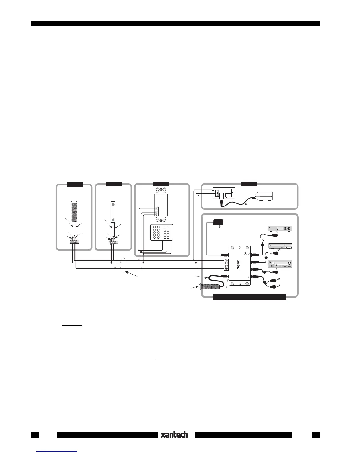
Fig. 2 A Typical 789-44 System
3. (Cont'd)
• For example, 2 keypads and several IR receivers could be used with one 781RG Power Supply and
12 keypads and 8 (or more) receivers could be used with one 782-00 Power Supply.
NOTE: To avoid current "hogging", never connect regulated power supplies, such as the 781RG or
the 782-00, in parallel!
• CAUTION: Do not use unregulated 12V power supply adapters from other manufacturers. These
may deliver excessive voltage to the IR receivers and cause them to “latch-up”. When this occurs,
the “talkback” LEDs and 283 Blink IR's (if used) will stay on continuously!
4. For clarity, connections in Fig. 2 are shown going to a 3-conductor bus in a "daisy chain" fashion. In
an actual installation, however, it is recommended that 4-conductor "home-runs" be pulled from each
room to the 789-44 Connecting Block in the main room. The home-runs maintain higher power supply
voltage to each IR receiver and keypad, and the extra 4th wire can be used for "STATUS" if desired
(refer to Fig. 3).
5. The "IR RCVR" jack on the 789-44 allows the 490-30 (and other Xantech IR Receivers with a cable
having a 3.5 mm stereo mini plug) to be plugged directly into the 789-44. You can do this when the
789-44 Connecting Block is within reach of the 7-foot cable, such as when installing the 490-30 in a
cabinet where the controlled equipment is behind closed doors.
CAUTION: Plug only Xantech IR Receivers equipped with a stereo mini plug into the IR RCVR
jack.
Do not plug in emitters or other devices; it will destroy emitter & damage power supplies!
6. The emitter ports are driven in parallel with a 470 Ohm resistor connected in series with each port. The
resistors ensure proper current sharing to each emitter. When using less than 4 emitters, you may plug
them into any of the 4 emitter ports without regard to order.
7. Because of this current sharing feature,
you may plug in any combination of the 282, 283, 284 & 286
series of emitters (up to a maximum of 8 individual emitters) to drive the desired number of devices.
NOTE: Be sure the 781RG Power Supply is plugged into an un-switched AC outlet. This maintains the
system in "standby" operation so that power-on commands can be sent to the controlled equipment.
OUT
V
IR
RCVR
PWR
GS
789-44
Connecting Block
Satellite Receiver
AV Receiver
VCR
MAIN ROOM, EQUIPMENT CABINET, ETC.
To 120 V AC
(unswitched; see
NOTE, item 7)
781RG
Power
Supply
282M
Emitter
283M
Blink IR™
7 Foot 3-Conductor
Cable with Quick
Connect Stereo Mini Plug
490-30
Series
Micro Link™
IR Receivers
291-10
Hidden Link™
IR Receiver
GND
IR OUT
+12V
ROOM 3
780-10
J-Box
IR Receiver
490-00
Series
Micro Link™
IR Receivers
3-Wire
Cable
IR OUT
GND
+12V
480-00
Dinky Link™
IR Receiver
Red
Stripe
Smart
Pad™
GND
IR OUT
+12V
ROOM 2
ROOM 1
ROOM 4
GND
IR OUT
+12V
286M
Dual Blink IR™
(to other
controlled
devices)
3-Wire
Cable
IR OUT
GND
+12V
Red
Stripe
+12V
IR OUT
GND
780-10
J-BOX RECEIVER
XANTECH CORPORATION
SYLMAR, CA 91342
CAUTION:
See text, item 5.
7 Foot Quick
Connect Cable
CB12
Connecting
Block
12VDC
+12 VDC
GND
STATUS
IR IN
EMITTERS
IR
RCVR
789-44
CONNECTING BLOCK
®
282M
Emitter
 Loading...