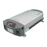
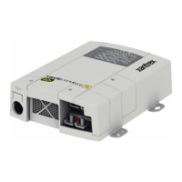
AC/DC and GFCI Panel
975-0784-01-01 9
Item Description
7 DC terminal opening for routing (+) positive DC cable.
8 LED alert indicator for reverse DC polarity.
9 AC output terminal opening for routing AC output wiring.
10 AC input terminal opening for routing AC input wiring.
11
GFCI cover is removed when installing a qualified GFCI
device such as the optional GFCI kit (sold separately;
order PN: 808-9817).
12
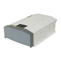
Mounting flanges on both sides allow you to mount the
inverter/charger permanently on the interior deck or on a
wall.
13
Ventilation grille (openings) must not be obstructed for
the proper operation of the cooling fan and
inverter/charger. When the inverter/charger is mounted,
the ventilation grille must not point up or down.
Cooling fans turn on when the internal temperature
reaches a set point temperature.
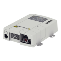
14
20 A supplementary protector with reset button
provides overload protection for the optional GFCI kit (sold
separately; order PN: 808-9817). Press to recover from an
overload condition. In a hard wired installation, the
supplementary protector does not protect output wiring.
WARNING
ELECTRICAL SHOCK HAZARD
n Use a torque screwdriver to tighten the bolt on the DC
ground lug to a torque of 23 in-lb (2.6 N-m) of force.
n Apply an anti-corrosion compound to the copper wire prior
to connecting to the DC ground lug.
Failure to follow these instructions can result in death, serious
injury, or equipment damage.
 Loading...