Communications Wiring for Multiple Inverters
975-0466-01-01 3–11
Xanbus Network Technology
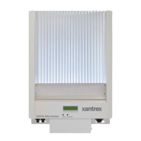
GT Inverters are Xanbus-enabled devices. They use Xanbus (a communications
protocol developed by Xantrex) to communicate with other GT Inverters. Each
GT Inverter is connected by an CAT5 cable, as shown in Figure 3-8.
Table 3-2 provides information on maximum Xanbus network length.
Figure 3-8
Network Layout (Communication Ports Cover Not Installed)
CAUTION: Equipment damage
Connect only Xanbus-enabled devices.
Although the cabling and connectors used in this network system are the same as Ethernet
connectors, this network is not an Ethernet system. Equipment damage may result from
attempting to connect Xanbus to different systems.
CAT5 cables
TerminatorTerminator
Table 3-2
Total Xanbus Network Length
Xanbus Baud Rate Total Xanbus Network Length
250 kbps 40 m (130 ft )
125 kbps 300 m (1000 ft)
Important:
Xanbus baud rate is set to 250 kbps by default. If you want to switch to 125
kbps, make sure to follow the recommended procedure supplied by Xantrex. See the
Application Note, “Xantrex Grid Tie Solar Inverter Baud Rate Change Procedure”
(976-0216-01-01 available on www.xantrex.com).
Important:
Remote upgrade using the Xantrex Communications Gateway is not sup-
ported on systems with a 125 kbps baud rate. If you change the baud rate to 125 kbps, then
you will no longer be able to use the Gateway to upgrade the firmware on GT inverters.
You will have to upgrade each inverter in the system using an RS-232 cable and a laptop.
 Loading...