Revision A xi
List of Figures
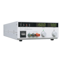
Figure 1.1 Power Supply Front Panel . . . . . . . . . . . . . . . . . . . . . . . . . . . . . . . . 17
Figure 1.2 Rear Panel with Bus Bar. . . . . . . . . . . . . . . . . . . . . . . . . . . . . . . . . . 18
Figure 1.3 Rear Panel with High Voltage Output Connector . . . . . . . . . . . . . . . 19
Figure 1.4 SW1 Programming Switch . . . . . . . . . . . . . . . . . . . . . . . . . . . . . . . . 19
Figure 1.5 J2 Programming Connector . . . . . . . . . . . . . . . . . . . . . . . . . . . . . . . 21
Figure 1.6 Dimensional Drawings . . . . . . . . . . . . . . . . . . . . . . . . . . . . . . . . . . . 30
Figure 2.1 Shipping or Storage Carton Label . . . . . . . . . . . . . . . . . . . . . . . . . . 34
Figure 2.2 Maximum Load Wire Length for 1 V Line Drop. . . . . . . . . . . . . . . . . 40
Figure 2.3 Bus Bar Shield . . . . . . . . . . . . . . . . . . . . . . . . . . . . . . . . . . . . . . . . . 42
Figure 2.4 Typical Load Connection Hardware . . . . . . . . . . . . . . . . . . . . . . . . . 43
Figure 2.5 Output Connector . . . . . . . . . . . . . . . . . . . . . . . . . . . . . . . . . . . . . . . 44
Figure 2.6 Single Load with Local Sensing (Default) . . . . . . . . . . . . . . . . . . . . . 45
Figure 2.7 Single Load with Remote Sensing . . . . . . . . . . . . . . . . . . . . . . . . . . 45
Figure 2.8 Multiple Loads with Local Sensing . . . . . . . . . . . . . . . . . . . . . . . . . . 46
Figure 2.9 Multiple Loads with Remote Sensing . . . . . . . . . . . . . . . . . . . . . . . . 47
Figure 2.10 Connecting Remote Sense Lines . . . . . . . . . . . . . . . . . . . . . . . . . . . 50
Figure 3.1 Operating Modes . . . . . . . . . . . . . . . . . . . . . . . . . . . . . . . . . . . . . . . 52
Figure 3.2 Series Operation of Multiple Supplies. . . . . . . . . . . . . . . . . . . . . . . . 55
Figure 3.3 Parallel Operation of Multiple Supplies. . . . . . . . . . . . . . . . . . . . . . . 56
Figure 3.4 Split Supply Operation of Multiple Supplies . . . . . . . . . . . . . . . . . . . 57
Figure 3.5 Split Supply Operation of Multiple Supplies . . . . . . . . . . . . . . . . . . . 58
Figure 3.6 Shutdown Programming with Active Low Signal . . . . . . . . . . . . . . . 62
Figure 3.7 Shutdown Programming with Active High Signal . . . . . . . . . . . . . . . 62
Figure 4.1 Connecting Programming Sources to J2 Connector . . . . . . . . . . . . 70
Figure 4.2 Sample Analog Programming Configuration . . . . . . . . . . . . . . . . . . 70
Figure 4.3 0-5 Vdc Output Voltage and Current Monitoring. . . . . . . . . . . . . . . . 71
Figure 4.4 0-10 Vdc Output Voltage and Current Monitoring. . . . . . . . . . . . . . . 72
Figure 5.1 Front Panel Calibration Locations. . . . . . . . . . . . . . . . . . . . . . . . . . . 76
Figure 5.2 Voltage and Current Programming Calibration Locations . . . . . . . . 78
Figure 5.3 Voltage Current and Monitor Calibration Locations . . . . . . . . . . . . . 80
TM-XROP-01XN.book Page xi Monday, March 22, 2004 4:10 PM
 Loading...