Features and Specifications
Mechanical Specifications
Revision A 29
Mechanical Specifications
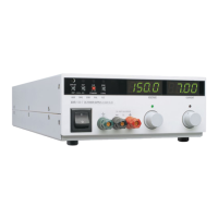
Front Panel Voltage and Current
Control
10-turn voltage and current potentiometers
Front Panel Voltage Control
Resolution
0.02% of maximum voltage
Front Panel Voltage and Current
Meters
3.5-digit numeric LED displays (for accuracy
specifications, see Table 1.2 and Table 1.3)
AC Input Connector Type IEC 320 Connector, appropriate power cord
for destination country.
Front Panel Output 5-way binding posts:
maximum current limit 30 A
OVP Control Screwdriver-set potentiometer on front panel
Input Fuses 20 A, 250 V, 5 x 20 mm slow fuses,
location: A5 PCB, F321, 325;
0.005 A, 250 V, 5 x 20 mm fast fuse,
location: A3 PCB, F1.
Main Output Connector 7.5 V to 40 V models: nickel-plated copper
bus bars;
60 V to 600 V models: 4-terminal wire clamp
connector for DC output and local sense.
Analog Programming, Monitoring,
and Sense Connector (2-piece)
12-terminal wire clamp connector
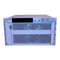
Chassis Ground Chassis ground screw located on rear panel
for bonding connections
Cooling Fan cooled. Air exhausts to rear. Over
temperature shutdown: automatic restart or
latch off (switch-selectable).
Mounting Optional rack mount pan. (RM3-XHR)
Size (one unit) 87.0 mm H x 214.6 mm W x 472.2 mm D
(3.425in. H x 8.45in. W x 18.59in. D)
Weight (one unit) Approximately 6.4 kg (14 lb.)
TM-XROP-01XN.book Page 29 Monday, March 22, 2004 4:10 PM
 Loading...