2
SALUT
Thank you for purchasing this Xaoc Devices
product. Odessa is an additive oscil-
lator, which means the output signal is syn-
thesized by adding a multitude of sinusoidal
components (up to 2560 harmonic partials).
By manipulating their parameters it is possible
to obtain a broad range of unearthly sounds as
well as classic saw, square, and pure sine. Odes-
sa offers a set of controls for shaping harmonic
spectra based on number of partials and their
distribution in frequency and amplitude; all
of which is illustrated by a spectrum analyzer
comprising 12 multicolor LEDs. The series of
harmonics can be squeezed or spread apart,
tilted, or pruned by a comb-like frequency re-
sponse, resulting in a huge variety of spectra.
Animating the comb response yields radical
partials are frequency-related to a common
fundamental and controlled by a single volt/
octave input. Additionally, the signal can be fre-
quency modulated by exponential and linear
voices can be spread apart for a fat and dense
cluster, or a powerful chord.
INSTALLATION & SETUP
The module requires 24hp worth of free space
in the eurorack cabinet. Always turn the pow-
er off before plugging the module into the bus
board using the supplied ribbon cable. Pay
close attention to power cable pinout and
orientation. The red stripe indicates the neg-
ative rail and should match the dot or –12V
mark on both the bus board and the unit.
Odessa is internally secured against reversed
power connection, however, rotating the 16-
pin header may cause serious damage to
other components of your system because
it will short circuit the +12V and +5V power
lines. Always pay particularly close attention
to the proper orientation of your ribbon cable
on both sides! Also, observe that there are sev-
eral pin headers on the board. connecting
the power cable to an incorrect head-
er will destroy your odessa! The unit
should be fastened by mounting the supplied
screws before powering up. To better under-
stand the device, we strongly advise the user
to read through the entire manual before use.
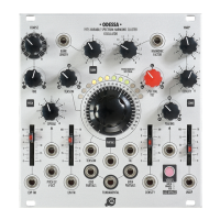
MODULE OVERVIEW
-
rect access to all parameters in a one-knob-
per-function arrangement. Observe that it
also follows the traditional synthesis layout,
wherein pitch and voicing are controlled on
the left side, the main timbral features are
centrally located, and additional effects are
controlled at the right. Signal outputs are
located in the bottom array of jacks. The arc
of multicolor LEDs offers a rough overview of
the spectrum of the signal, from very low to
the highest audible frequencies.
Pitch frequency is controlled via the pitch
cv v/oct input
1
which accepts voltages
in –5V…+10V range. The coarse
2
and
fine
3
pair of potentiometers set the pitch
throughout the entire audible range (16Hz to
20kHz) without the need for external voltage.
Additionally, pitch can be modulated from the
exp fm input
4
that accepts ±5V, with depth
controlled by the dedicated attenuator above
5
. As with other Xaoc Devices products, the
slider LED illuminates to show the absolute
degree of modulation by lighting up for both
negative and positive voltages. Bear in mind
that while the pitch knobs alone cover the
entire frequency range, at extreme knob po-
sitions modulation from the exp fm input will
module
explained
 Loading...