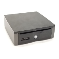
USB 2.0 Ports
ODD Eject Button
Power Button
Optical Device Drive
USB 2.0ࡐ࠻
USB 2.0 ࡐ࠻
USB 2.0 䗷ප
ܹᓣܝ″
ܝ″䗔⠛ᣝ䟩
Part No.: 49.MA501.0010 Doc. No.: MP57-EG-E1003B
Accessories List
Screw of SATA Card (2 pcs)
SATA ࠞ࠼↪ࡀࠫ㧔2㧕
SATA 㶎㍆㧔2业㧕
Riser Card
Riser ࠞ࠼
Riser
90W DC 20V Power Adapter
90W DCࠕ࠳ࡊ࠲
90W DC䅞ວ఼
S/PDIF Converter
S/PDIFࠦࡦࡃ࠲
S/PDIF 䔝丁
Power Cord (by Territory)
㔚Ḯࠦ࠼㧔ᣣᧄ࿖ౝ↪㧕
䳏⑤㎮ഄ㗠ᅮ
Driver CD
࠼ࠗࡃCD
候ࢩᓣܝ⠛
EIG
◲න⚵ߺ┙ߡࠟࠗ࠼
ㇵᯧᅝ㺱ᣛ
Mainboard Overview
Screw of HDD (4pcs)
HDDࡀࠫ㧔4㧕
HDD㶎㍆㧔4业㧕
Easy Installation Guide
AOpen reserves the right to revise all the specifications and information contained in this document, which are subject
to change without notice.
DVI to VGA Converter (by model)
DVI to VGA
ࠦࡦࡃ࠲(ࡕ࠺࡞ߦࠃߞߡ)
DVI to VGA ヱធ㗡(ձൟ㰳㗠ᅮ)
DVI to DVI + D-Sub Cable (by model)
DVI to DVI + D-Sub ࠤࡉ࡞
(ࡕ࠺࡞ߦࠃߞߡ)
DVI to DVI + D-Sub䗷㎮
(ձൟ㰳㗠ᅮ)
Wireless Antenna (by model)
ࡢࠗࡗࠬࠕࡦ࠹࠽(ࡕ࠺࡞ߦࠃߞߡ)
Wireless Antenna (ձൟ㰳㗠ᅮ)
Support Module List
Screw of Blue-Tooth (1 pcs)
Blue-Tooth ↪ࡀࠫ㧔1㧕
Blue-Tooth㶎㍆㧔1业㧕
AOpen ߪᒰᢥᦠߦ߹ࠇࠆߔߴߡߩ᭽߅ࠃ߮ᖱႎࠍᡷቯߔࠆᮭࠍߒߡ߅ࠅޔ๔ߥߒߢᄌᦝߐߖߡ
ߚߛߊ႐ว߇ߏߑ߹ߔޕ
ࠕࠢࠨࠬ࠻
䜡ӊ㸼
ኻᔕࡕࠫࡘ࡞ࠬ࠻
ᬃᧈ䷙Ⳃ
ߒߊߪޔຠRCLߩࡍࠫȐhttp://global.aopen.com/RCL.aspxȑࠍߏෳᾖߊߛߐޕ
Intel Core i3 CPU ߪ vPro 㕖ኻᔕߢߔޕ
ࡔࠗࡦࡏ࠼ߩⷐ
Џ″ᵓὖ㽕
ᢚ㋏㍅
1. Disassemble the System
Note: With CPU speed changing rapidly, there might be faster CPU on the market by the time you
received this installation guide. This table is kindly for your references only.
ᵈᗧ㧦ߎߩ৻ⷩߪߊ߹ߢ߽ෳ⠨ߣߒߡߏ↪ߊߛߐޕCPU ߩઍઍ߇ടㅦߒߡ߅ࠅޔ߅ቴ᭽߇
ߎߩࡑ࠾ࡘࠕ࡞ࠍෳᾖߐࠇࠆ㗃ߦߪޔߎߩߦ⸥タߐࠇߡࠆએߩㅦᐲߩ CPU ߇Ꮢ႐ߦ࿁ߞ
ߡࠆน⢻ᕈ߇ࠅ߹ߔޕ
⊼ᛣ⬅ᮐ⫶ક䱇ߎᮄǃᖿ䗳䗁ˈ᠔ҹ㸼߫ڙկগ㗗ˈ⫶ક㽣Ḑҹߎଂᆺ⠽⚎⑪DŽ
Please refer to RCL link: http://global.aopen.com/RCL.aspx
ߎߩ৻ⷩߪߊ߹ߢ߽ෳ⠨ߣߒߡߏ↪ߊߛߐޕhttp://global.aopen.com/RCL.aspx
䂟গ㗗RCL 䗷㌤: http://global.aopen.com/RCL.aspx
CPU Frequency Table
3. Install Memory Modules
2.4 CPU socket lock
Use the Slotted(-) screwdriver to turn CPU socket
screw toward the Lock mark. (Clockwise direction)
CPU ࠰ࠤ࠶࠻ࠍࡠ࠶ࠢߔࠆ
ࡑࠗ࠽ࠬ࠼ࠗࡃࠍޔ%27࠰ࠤ࠶࠻ࡆࠬࠍޟUnlockޠ
߆ࠄޟLockޠߩᣇะ߳߹ࠊߒ߹ߔ㧔ᤨ⸘࿁ࠅ㧕ޕ
CPU ᦦῑ䥪ԣ
Փ⫼ϔᄫ䍋ᄤ՚ᮟ䔝
CPU
ᦦᑻ㶎㍆ˈᣛ䥪ԣⱘᮍ
䷚ᰖ䞱ᮍDŽ
Note: When screw the socket. You will hear a slight sound "Dock". That means you already installed CPU successfully.
ᵈᗧ㧦CPU ࠍ⏕ታߦ࿕ቯߔࠆߚޔࡑࠗ࠽ࠬ࠼ࠗࡃࠍシߊ㖸߇ߔࠆ߹ߢ߹ࠊߒߡߊߛߐޕ
⊼ᛣ⭊ᮟ䔝
CPU
ᦦᑻ㶎㍆ᰖˈᙼ᳗㙑ࠄ㌄ᖂⱘԣ㙆䷇ˈ䙷㸼⼎ᙼᏆ㍧៤ࡳᅝ㺱њ
CPU
㰩⧚఼DŽ
SODIMM slots are designed in high and low positions which are very easy to recognize.
Insert the module straight down to the SODIMM slot with fingers and press down firmly until the
SODIMM module is securely in place.
SO-DIMM
ࠬࡠ࠶࠻ߪ߿ߔ▎ᚲߦޔᲑߦᝪ߃ઃߌࠄࠇߡ߹ߔޕ
SO-DIMM
ࠬࡠ࠶࠻ߦࡔࡕ
ࡕࠫࡘ࡞ࠍะ߈ߦᏅߒㄟߺޔᜰߢߒߞ߆ࠅߣ࿕ቯߒߡߊߛߐޕ
SODIMM ᦦῑ䀁㿜៤催Ԣԡ㕂ߚᆍᯧ䕼䄬ˈᦦܹ㌘ᰖ䂟ⳈᬒܹSODIMMᦦῑϺϨ⫼ᣛ䗕ࠄᅮԡDŽ
3.3 Plug in memory module into SODIMM slot with angle 20 ~ 30°.
Make sure memory module plug into slot completely.
20ɴ30°
ߩⷺᐲߢޔᣂߒࡔࡕࠍ
SO-DIMM
ࠬࡠ࠶࠻ߦᝌߒ߹ߔޕ
ࡔࡕߪᅏ߹ߢ⏕ታߦᏅߒㄟࠎߢߊߛߐޕ
ҹ20 ~ 30°㾦ᇛ㿬ដ储㌘ᦦܹSODIMM ᦦῑˈϺ⺎䁡Ꮖ㍧ℷ⺎ᬒ㕂ࠄᅮԡDŽ
3.4 Using finger to push memory module vertically until the tabs lock memory module tightly.
now, the memory modules have been plugged in properly with horizontal flat.
ࡔࡕࠍ߆ࠄု⋥ߦߒㄟߺޔ࿕ቯ↪࠷ࡔߢߒߞ߆ࠅߣ࿕ቯߒ߹ߔޕ
ࡔࡕࡕࠫࡘ࡞߇᳓ᐔߦ࿕ቯߐࠇߚࠄޔࡔࡕߩขࠅઃߌߪቢߢߔޕ
ҹᣛᇛ㿬ដ储㌘ൖⳈວϟ㟇䞺㎞⚎ℶˈ⧒㿬ដ储㌘Ꮖ㍧ᅠܼᑇᭈⱘ㕂ܹᦦῑЁDŽ
Figure 3.2
Figure 3.4
1.2 Distribute the Bare bone into two modules. • Bottom Case module. • Upper Case module.
ᧄࠍࠤࠬㇱߣࠤࠬㇱߩ 2 ߟߦಽ⸃ߒ߹ߔޕ• ࠤࠬㇱ• ࠤࠬㇱ
ᇛ⑪㋏㍅ߚ䭟⚎ܽן㌘• ϟሸ㌘• Ϟሸ㌘
Figure 1.2-1
Bottom Case module
ࠤࠬㇱ
ϟሸ㌘
2. Install CPU
2.2 CPU socket unlock
Use the Slotted(-) screwdriver to turn CPU socket screw toward the unlock mark. (Anticlockwise direction)
CPU ࠰ࠤ࠶࠻ߩࠕࡦࡠ࠶ࠢ
ࡑࠗ࠽ࠬ࠼ࠗࡃࠍޔCPU࠰ࠤ࠶࠻ࡆࠬࠍȨ
Lock
ȩ߆ࠄޟUnlockޠߩᣇะ߳߹ࠊߒ߹ߔ㧔ᤨ⸘࿁ࠅ㧕ޕ
CPU ᦦῑ䭟䥪
Փ⫼ϔᄫ䍋ᄤ՚ᮟ䔝 CPU ᦦᑻ㶎㍆ˈᣛ䭟䥪ⱘᮍডᰖ䞱ᮍDŽ
Caution: If you do not match the CPU Socket Pin1 and CPU Golden arrow well, you may damage the CPU.
⼊๔㧦࠰ࠤ࠶࠻⇟ࡇࡦߣ⍫ශߩ⟎߇ߕࠇࠆߣޔCPU ࠍ៊்ߔࠆᕟࠇ߇ࠅ߹ߔޕ
䄺བᵰᙼᇛ CPU ᦦᑻϔ䞱㝇㟛 CPU 䞥㡆ㆁ丁ᇡ唞ᇛৃ㛑ᇢ㟈 CPU ᧡າDŽ
2.3 Upgrade New CPU
Remove existing CPU, then install a new CPU. Locate Pin 1 in the socket and look for a golden arrow
on the CPU upper interface. Match Pin 1 and golden arrow. Then insert the CPU into the socket.
ᣂߒCPU ߩขࠅઃߌ
ᣢሽߩCPU ߇ࠆ႐วߪขࠅᄖߒޔᣂߒCPU ࠍขࠅઃߌ߹ߔޕCPUߩ߰ߜߦࠆ㊄⦡ߩ
ٌߩ⍫ශࠍޔCPU ࠰ࠤ࠶࠻⇟ࡇࡦߣหߓ⟎ߦวࠊߖߡޔCPUࠍ࠰ࠤ࠶࠻ߦᝌߒ߹ߔޕ
㋮ᮄⱘ CPU
⿏䰸ⳂࠡⱘCPU✊ᕠᅝ㺱ᮄⱘCPUDŽܜᡒߎϔ䞱㝇ⱘԡ㕂ˈ✊ᕠᡒࠄCPU
㚠Ϟⱘ䞥㡆ㆁ丁DŽܽ㗙ⱚ⺎䁡ПᕠݡᇛCPUᅝ㺱&38ᦦᑻЁDŽ
Figure
2.2-1
Figure
2.2-2
Figure 2.3-1 Figure 2.3-2
2.1 Take the bottom module.
Unfix 2 pcs screws of the thermal module. Don’t unplug the cooler cable. Remove the thermal
module carefully as figure 2.1-1. Don’t unplug the thermal module cable. Remove and put it on
the table as figure 2.1-2.
ࠤࠬㇱߦࠆࡅ࠻ࠪࡦࠢߩࡀࠫ㧔2 ▎ᚲ㧕ࠍᄖߒ߹ߔޕ
ࡅ࠻ࠪࡦࠢࠤࡉ࡞ߪᛮ߆ߥߢߊߛߐޕ࿑ 2.1-1 ߩࠃ߁ߦޔࠤࡉ࡞ࠍᧄߦធ⛯ߒߚ
߹߹ࡅ࠻ࠪࡦࠢߩߺࠍᧄ߆ࠄᄖߒޔᬺบߩߦ⟎ߡߊߛߐޕ
ᣓ䍋ϟሸ㌘
ᢚ䰸ᬷ➅఼㌘ⱘ业㶎㍆ˈܜϡ㽕ᢨ䰸ᬷ➅఼ⱘ䗷㎮DŽᇣᖗ⿏䭟ᬷ➅఼㌘བ೪2.1-1ˈϡ㽕
ᢚᬷ➅఼㌘䗷㎮DŽ㗏䭟ᕠᬒḠ䴶Ϟབ೪2.1-2DŽ
Figure 2.1-1 Figure 2.1-2
Unlock
Lock
Socket Screw
Socket Pin1
Unlock
Socket Pin1
Golden Arrow
Figure 2.4
Lock
Key
Tab
Tab
20°~30°20°~30°
20°~30°20°~30°
Battery Connector
㔚Ḯࠦࡀࠢ࠲
䳏∴ষ
Riser Card Connector
ࠗࠩࠞ࠼ࠦࡀࠢ࠲
Riser ᦦῑ
mini Card Half Size Slot
mini Card ࠬࡠ࠶࠻㧔ࡂࡈࠨࠗ࠭68࠴ࡘ࠽ࡕࠫࡘ࡞↪㧕
䗋Դᦦῑ
CPU Fan Connector
CPU FAN ࠦࡀࠢ࠲
CPU 乼ষ
mini Card Standard Slot
mini Card ࠬࡠ࠶࠻㧔ࠬ࠲ࡦ࠳࠼ࠨࠗ࠭9K(Kࡕࠫࡘ࡞↪㧕
䗋Դ῭⑪ᦦῑ
Front USB2.0 Connector
ࡈࡠࡦ࠻ USB 2.0 ࠦࡀࠢ࠲
ࠡ䴶ᵓ USB 2.0 ষ
3.3V USB 2.0 Connector (for 3.3V Bluetooth Module)
3.3V USB 2.0 ࠦࡀࠢ࠲Ȑ3.3V Bluetoothࡕࠫࡘ࡞↪ȑ
3.3V USB 2.0 ষ (կ 3.3V 㮡⠭㌘Փ⫼)
Rear Panel
ᓟㇱࡄࡀ࡞
ᕠ䴶ᵓ
LPC Connector
LPC ࠦࡀࠢ࠲
LPC ষ
Intel Chipset
Intel ࠴࠶ࡊ࠶࠻
Intel ⠛㌘
DDRIII SODIMM
࠺ࡘࠕ࡞࠴ࡖࡦࡀ࡞ࡕ࠼ DDR3 SODIMM
DDRIII SODIMM
Intel Mobile CPU Socket
Intel Mobile CPU ࠰ࠤ࠶࠻
Intel Mobile Ё༂㰩⧚఼ᦦῑ
USB Connector
USB ࠦࡀࠢ࠲
USB ষ
Power Switch Board Connector
㔚Ḯࠬࠗ࠶࠴ࡏ࠼ࠦࡀࠢ࠲
䳏⑤䭟䮰ᵓষ
1
2
3
4
5
6
7
9
10
11
12
13
14
8
CPU INTEL i7-620M Arrandale 32nm,2.66GHz,4MB L3 Љ35Wdz
CPU INTEL i5-540M Arrandale 32nm,2.53GHz,3MB L3 dz Љ35W
CPU INTEL i5-520M Arrandale 32nm,2.40GHz,3MB L3 dz Љ35W
CPU INTEL i5-430M Arrandale 32nm,2.266GHz,3MB L3 Γ!!!Љ35W
CPU INTEL i3-330M (TJ90) Arrandale 32nm,2.13GHz,3MB L3 dz Љ35W
CPU INTEL i3-350M(TJ90) Arrandale 32nm,2.266GHz,3MB L3 Љ35W
Model-Supplier P/NItem Vendor Description
Power Consumption
Note:
The power switch is designed as electronic sensor type, not
mechanical. When you would like to turn on the system, please
let your tumb touch the power icon for one to three seconds.
For safety, not allow to remove this cover.
ㇱࠞࡃߪᄖߐߥߢߊߛߐޕ⎕៊ߩේ࿃ߣߥࠅ߹ߔޕ
⚎ᅝܼ䍋㽟ˈ䂟࣓ᠧ䭟Ϟ㪟DŽ
Item ຠฬ䷙Ⳃ
ODD
శቇ࠼ࠗࡉ
ܝ″
CPU
CPU
Ё༂㰩⧚఼
HDD
HDD
⹀
Memory
ࡔࡕ
㿬ដ储
WiFi module
WiFi ࡕࠫࡘ࡞
WiFi ㌘
Descriptionౝኈܻᆍ
Standard Slim type / Slot-in ODD
ᮡḰࠬࡓ࠲ࠗࡊࠬࡠ࠶࠻ࠗࡦᑼశቇ࠼ࠗࡉ
ᮡḰ⭯ဳ/ ๆᑼశ⏅ᯏ
Intel Core i3 / i5 / i7 series CPU (ɩ35W)
Intel Core i3 / i5 / i7 ࠪ࠭ CPU (ɩ35W)
Intel Core i3 / i5 / i7㋏߫CPU (ɩ35W)
2.5” HDD SATA interface
2.5ࠗࡦ࠴ SATA ࠗࡦ࠲ࡈࠚࠗࠬHDD
2.5 㣅য় SATA ⹀ҟ䴶
DDR III SO-DIMM
DDR III SO-DIMM
DDR III SO-DIMM
Standard mini card interface WiFi module
ᮡḰ mini card ࠗࡦ࠲ࡈࠚࠬWiFi ࡕࠫࡘ࡞
῭⑪䗋Դҟ䴶 WiFi ㌘
Remark ⠨٭䀏
By model
ࡕ࠺࡞ߦࠃߞߡ
ձൟ㰳㗠ᅮ
Option
ࠝࡊ࡚ࠪࡦ
ㆬ⾼㈩
Option
ࠝࡊ࡚ࠪࡦ
ㆬ⾼㈩
Option
ࠝࡊ࡚ࠪࡦ
ㆬ⾼㈩
Option
ࠝࡊ࡚ࠪࡦ
ㆬ⾼㈩
* Please refer to RCL link: http://global.aopen.com/RCL.aspx
* Intel Core i3 CPU doesn’t support vPro.
Figure 1.3
Upper Case module
ࠤࠬㇱ
Ϟሸ㌘
Figure 1.2-2
Upper Case module
ࠤࠬㇱ
Ϟሸ㌘
Card Reader (Option)
ࠞ࠼࠳
㧔ࠝࡊ࡚ࠪࡦ㧕
䅔″䙌䋐䜡٭
Figure 2.5-1
1
2
3
4
Figure 2.5-2
ᵈᗧ㧦
㔚Ḯࠬࠗ࠶࠴ߪ㔚ሶࡦࠨߢേߒ߹ߔޕ㔚Ḯࠍࠇࠆ
㓙ߪ㔚Ḯࠕࠗࠦࡦࠍᜰߢ 1ɴ3 ⑽࠲࠶࠴ߒߡߊߛߐޕ
* 䂟গ㗗㎆キ䗷㌤: http://global.aopen.com/RCL.aspx
* Intel Core i3 CPU Ϻᬃᧈ vPro.
1
2
3
4
5
6
7
8
9
10
11
12
13
14
㨫㙆ᯢˈℸ㨫ቀᮐᓎ⹕㙵ӑ᳝䰤݀ৌ⠜᠔᳝DŽᓎ⹕㙵ӑ᳝䰤݀ৌ᳝ᮄℸݞⱘܻᆍˈ㗠ϡ䳔㽕
㸠䗮ⶹDŽ≦᳝ᓎ⹕㙵ӑ᳝䰤݀ৌџܜⱘ䴶䀅ৃࠡˈℸߎ⠜કϡᕫࡴҹ㻛㻑ǃᡘᆿǃڇ䗕ǃ㗏䅃៤ӏԩ䁲㿔ˈ
г⽕ℶҹ䳏ᄤၦ储ǃ″Ẅǃܝ⠛݊ҪӏԩᔶᓣᄬপDŽ
⊼ᛣ˖
䳏⑤䭟䮰⚎䳏ᄤᛳឝᓣ䴲″Ẅᓣᣝ䟩ˈ⭊ᙼ㽕ଳࢩ
㋏㍅ᰖˈ䂟ҹᢛᣛ㿌䳏⑤೪⼎ 1 㟇 3 ⾦DŽ
ಽ⸃ᣇᴺ
1.1 Open Chassis ࠪࡖࠪࠍ㐿ߌࠆ䭟ଳ″←
Remove 4 screws, open the Bare bone by pulling two opening labels.
Remove two opening labels and scratch them.
ࡊࠬ࠼ࠗࡃࠍߞߡᐩ㕙ߩࡀࠫ㧔4 ▎ᚲ㧕ࠍᄖߒ߹ߔޕ
㧔⍫ශߩ 2 ▎ᚲ㧕ࠍᒁߞᒛࠅߥ߇ࠄᧄࠍ㐿߈߹ߔޕ
ᢚϟ 4 业㶎㍆ˈᢝᡃ 2 ᔉ䭟ଳ䊐㋭✊ᕠᠧ䭟⑪㋏㍅DŽ
⿏䰸 2 ᔉ䊐㋭ϺϨࠂ䰸ђ⎼DŽ
Figure 1.1-1 Figure 1.1-2
1.3 Remove four screws of the supporter. Take the riser
card / card reader module from the little bag.
ࠤࠬㇱߩ㊄ౕߩࡀࠫ㧔4▎ᚲ㧕ࠍᄖߒޔ
ࠗࠩࠞ࠼ࠞ࠼࠳ࡕࠫࡘ࡞ࠍࠤ
ࠬ߆ࠄᄖߒ߹ߔޕ
ᢚϟᬃᶊⱘ4 业㶎㍆ˈᢚ䰸 Riser 䅔″㌘DŽ
ᅝ㺱CPUCPUߩࠗࡦࠬ࠻࡞ᣇᴺ
ኻᔕCPUᵄᢙ৻ⷩ CPU 丏⥛㸼
ᅝ㺱㿬ដ储㌘
2.5 Install CPU Cooler
Check the screw hole on mainboard before assemble the cooler, then tighten the 4 screws,
follow the sequence of operation from 1~4, and make sure the CPU cooler is fastened to the
mainboard, check again the fan cable still plug on mainboard.
ࡅ࠻ࠪࡦࠢߩขࠅઃߌ
ขࠅઃߌࠆ೨ߦࡔࠗࡦࡏ࠼ߩ
4
▎ᚲߩࡀࠫⓣࠍ⏕ߒޔࡅ࠻ࠪࡦࠢࠍరߩ⟎ߦᚯߒ߹ߔޕ
࿑
2.5-2
ߦ⸥ߐࠇߡࠆ㗅⇟ߦޔࡀࠫࠍ
4
▎ᚲขࠅઃߌޔࡅ࠻ࠪࡦࠢࠍࡔࠗࡦࡏ࠼ߦ࿕ቯߒ߹ߔޕ
࿕ቯߒߚࠄޔࠤࡉ࡞߇ࡔࠗࡦࡏ࠼߆ࠄᄖࠇߡߥ߆ౣᐲ⏕ߒߡߊߛߐޕ
ᅝ㺱CPU ᬷ➅఼
㌘㺱ᬷ➅఼ࠡܜᡒࠄЏ″ᵓϞⱘ㶎㍆ᄨˈᣝ✻೪⼎䷚ᑣ䥪Ϟ业㶎㍆ˈ⺎ᅮCPU ᬷ➅఼Ꮖ㍧
䥪㎞Џ″ᵓϞˈݡ⁶ᶹ乼ᰃ৺ҡ✊䗷ᮐЏ″ᵓϞDŽ
ࡔࡕߩขࠅઃߌ
3.1 There're tabs which located in the side of SODIMM holder. Detach the existing memory from
the memory slot.
SO-DIMM ࠬࡠ࠶࠻ౝㇱߦߪޔࡔࡕ࿕ቯ↪ߩ࠷ࡔ߇ࠅ߹ߔޕᣢሽߩࡔࡕ߇ࠆ႐วߪޔ
࿕ቯ↪࠷ࡔࠍߒᐢߍߡ㐿ߒޔࡔࡕࡕࠫࡘ࡞ࠍขࠅᄖߒ߹ߔޕ
᳝ϔᇡߚ߹SODIMM ܽو༒㞖Ϟˈߚ䭟ᕲ㿬ដ储ᦦῑϞ⿏䰸㟞ⱘ㿬ដ储DŽ
3.2 Put the memory module with correct direction. Notice there's one key position to make sure
direction is correct.
ᣂߒࡔࡕࡕࠫࡘ࡞ߣࠬࡠ࠶࠻ߩಾࠅᰳߌ⟎ࠍวࠊߖޔࡔࡕࠍᱜߒะ߈ߦᝌߒㄟߺ߹ߔޕ
ᇛ㿬ដ储㌘ᬒܹˈ䂟⊼ᛣ᳝ϔןᅮԡῑˈҹℸ⁶ᶹԡ㕂ᰃ৺ℷ⺎DŽ
DVI-I Port
USB 2.0 Ports
RJ45 LAN Jack
20V DC Jack
Kensington Lock
Line in (S/PDIF Out)
Line Out
Microphone
eSATA Port
eSATA ࡐ࠻
eSATA 䗷ප
HDMI Port
HDMI ࡐ࠻
HDMI 䗷ප
Power DVD (by model)
Power DVD (ࡕ࠺࡞ߦࠃߞߡ)
Power DVD (ձൟ㰳㗠ᅮ)
◲න⚵┙ࠟࠗ࠼
ㇵᯧᅝ㺱ᣛ
శቇ࠼ࠗࡉ
DVD ขࠅߒࡏ࠲ࡦ
㔚Ḯࡏ࠲ࡦ
ࠗࡦജȐS/PDIFജȑ
ࠗࡦജ
ࡑࠗࠢജ
䔌ܹ(S/PDIF 䔌ߎ)
䔌ܹ
呹ܟ乼
USB 2.0 䗷ප
20V DCࠫࡖ࠶ࠢ
20V Ⳉ⌕䳏⑤ষ
DVI ജࡐ࠻
20V 䔌ߎষ
RJ45 LANࠫࡖ࠶ࠢ
ࠤࡦࠫࡦ࠻ࡦࡠ࠶ࠢࡎ࡞
Kensingtonᅝܼ䥪
RJ45 ㎆䏃ষ
䳏⑤ᣝ䟩