Do you have a question about the Xtender XTM 4000-48 and is the answer not in the manual?
Manual is part of the device, covers models and accessories.
Provides general safety warnings and notes for installation and use.
Manual must be kept available; installation and commissioning by qualified personnel.
Safety guidelines for handling and charging batteries.
Criteria for selecting a suitable installation location.
Installation site requirements for XTM and XTH models.
How to securely mount the Xtender unit.
Specific instructions for mounting the XTH model.
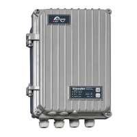
Specific instructions for mounting the XTM model.
Specific instructions for mounting the XTS model.
Essential guidelines for making electrical connections.
Essential guidelines for making electrical connections.
Details the connection compartment for XTH and XTM units.
Details the connection compartment for the XTS unit.
Lists and describes connection points for XTH, XTM, and XTS models.
Guidelines for proper earthing of the Xtender system.
Recommendations for protecting against lightning.
How to calculate required system components.
How to calculate the required battery capacity.
Selecting battery cables and protective devices.
Steps for connecting battery cables to the Xtender.
Procedures for connecting batteries, checking voltage and polarity.
Connecting loads to the Xtender's AC output.
Connecting external AC sources like grid or generator.
Basic parameter adjustments directly on the XTS model.
Procedures and warnings for connecting the battery.
How to power up the unit using the main switch.
Connecting loads to the Xtender output.
Activating input circuit breakers for power sources.
Details the automatic battery charging process.
Explains the multi-stage battery charging process.
Protection against deep discharge and voltage issues.
Electronic protection mechanisms of the Xtender.
How the unit handles output overloads.
Protection against battery overvoltage.
How overheating affects performance.
Protection against incorrect battery connection.
Combining Xtenders to create a three-phase system.
| Weight | 13 kg |
|---|---|
| Model | XTM 4000-48 |
| Nominal Battery Voltage | 48 V |
| Input Voltage Range | 38 - 68 Vdc |
| Output Voltage | 230 V |
| Output Frequency | 50 Hz |
| Cooling | Fan |