
F
fuenteskatherineAug 4, 2025
What to do if Xtralis VESDA Sensepoint XCL fail the bump test?
- JJoshua NelsonAug 4, 2025
If Xtralis Gas Detectors fail the bump test, replace the sensor cover or calibrate the device.
What to do if Xtralis VESDA Sensepoint XCL fail the bump test?
If Xtralis Gas Detectors fail the bump test, replace the sensor cover or calibrate the device.
What to do if Xtralis VESDA Sensepoint XCL Gas Detectors fail after replacing sensor cover or calibrating?
If Xtralis Gas Detectors fail after replacing the sensor cover or calibrating, replace the gas sensor or calibrate the device.
Details key features like analog, digital, and relay outputs, plus mobile app support.
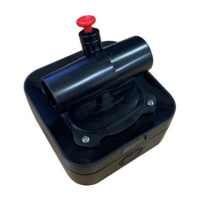
Illustrates the components of the gas detector with a labeled diagram.
Lists part numbers and descriptions for compatible accessories.
Lists the various gases the detector can identify and their units.
Explains different detector versions based on output type (mA, Modbus).
Describes the function of the two configurable relays for signaling.
Provides technical specifications including dimensions and weight.
Outlines crucial safety precautions to prevent injury and equipment damage during installation.
Shows typical wiring diagrams for Modbus and analog current loop systems.
Details power supply requirements and maximum cable lengths based on resistance.
Identifies and describes the components of the detector module itself.
Provides instructions and diagrams for wiring analog (mA) output versions, including inhibit levels.
Explains how to connect multiple detectors in a daisy chain for Modbus versions.
Guides on mounting the detector's back box securely to a wall surface.
Details how to fit cable glands and connect cables to the terminal blocks.
Emphasizes the importance of proper grounding to prevent interference and ensure stability.
Instructions for attaching the detector module and flow cap to the back box.
Describes how to connect the detector to the aspirating pipe network, including offsets.
Provides guidelines for flow monitoring and positioning of sample holes.
Explains factors influencing alarm level settings and refers to application notes.
Step-by-step guide for initial setup and configuration of the detector.
Explains the meaning of different colors and patterns of the status indicator LED.
Details how to select the target gas for flammable catalytic sensor versions.
Describes how to perform basic maintenance using the physical buttons on the detector.
Explains the indicator on the rear of the module for maintenance status.
Step-by-step instructions for zero and span calibration using the Sensepoint App or buttons.
Outlines the procedure for performing a bump test to verify sensor functionality.
Instructions for safely removing and replacing the sensor cover.
Detailed guide on how to change the gas sensor unit.
How to clear latched alarms and faults and initiate self-diagnostics.
Provides a flowchart for diagnosing issues during calibration and bump testing.
Guides on downloading, installing, and using the Sensepoint mobile application for device management.
Lists detailed parameters for various gas sensors, including ranges and accuracy.
Provides a list of common warnings and faults with their troubleshooting steps.
Lists part numbers for detectors, accessories, consumables, and spares.
Outlines the terms and conditions of the product warranty.
Covers FCC, IC, and RED compliance for wireless functionalities.
Details the Modbus registers for communication and data interrogation.
| Humidity Range | 0 - 99% RH (non-condensing) |
|---|---|
| Detection Method | Electrochemical |
| Gas Types | Toxic and Combustible Gases |
| Communication | Modbus, HART, 4-20 mA |
| Output | 4-20mA with HART, Modbus RTU |
| IP Rating | IP66 |
| Measurement Range | Depends on gas type |
| Outputs | 4-20 mA, Relay |
| Certifications | ATEX, IECEx, UL, CSA |