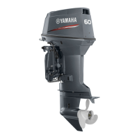
Do you have a question about the YAMAHA Marine 50G and is the answer not in the manual?
| Horsepower | 50 hp |
|---|---|
| Starting System | Electric |
| Cylinder | 3 |
| Full Throttle RPM Range | 5000 - 6000 rpm |
| Ignition | TCI |
| Lubrication | Wet Sump |
| Recommended Engine Oil | Yamalube 4M |
| Gear Shift | Forward, Neutral, Reverse |
| Shaft Length | 20 in |
| Maximum Horsepower | 50 hp |
| Displacement | 996 cc |
| Fuel System | EFI |
| Weight | 114 kg |
| Gear Ratio | 2.0:1 |
| Bore x Stroke | 65 mm x 75 mm |
| Recommended Fuel | Regular Unleaded Gasoline (minimum pump octane number 87) |
| WOT RPM | 5000 - 6000 rpm |
| Engine Type | 4-Stroke |
Details serial numbers, model names, and transom height for identification.
Guidelines for safe work practices, including fire prevention and ventilation.
Lists and describes specialized tools required for maintenance and repair.
Details procedures and tools for various measurements.
Outlines procedures for removing and installing components.
Provides overall dimensional and performance specifications for different models.
Lists critical maintenance specifications like clearances and tolerances.
Specifies torque values for engine, case, and other assemblies.
Provides general torque guidelines for standard fasteners.
Outlines a maintenance schedule with intervals and reference pages.
Describes inspection and replacement procedures for the anode.
Details safety precautions and capacity specifications for batteries.
Covers carburetor inspection, cleaning, and disassembly.
Explains how to adjust carburetor linkage for various engine models.
Provides procedures for retightening critical engine fasteners.
Details cleaning and inspection of the fuel filter components.
Covers checking fuel tank and line for leaks and cleaning.
Describes procedures for draining and refilling gear oil.
Explains how to adjust and set the engine idle speed.
Covers adjusting the timing plate position and ignition timing.
Details adjusting throttle sensor and cam link lengths.
Explains how to adjust the pick-up timing.
Covers operational testing of the oil injection pump.
Describes checking and topping up hydraulic fluid for PTT systems.
Details inspection of propeller blades and spline for damage.
Covers spark plug inspection, cleaning, and gap adjustment.
Identifies key points requiring grease application.
Overview of the fuel system, including exploded diagrams.
Details checking the correct installation of the fuel line.
Covers safety precautions and steps for fuel system removal.
Describes cleaning fuel tanks and inspecting fuel system parts.
Details cleaning and inspection of the fuel meter assembly.
Covers inspection of the priming pump and its check valve.
Describes disassembly and inspection of the fuel filter.
Details inspection of fuel joints for leaks and cracks.
Covers disassembly and inspection of the fuel pump components.
Provides steps for installing the fuel system components.
Covers exploded diagrams, removal, inspection, assembly, and installation of carburetors.
Details exploded diagrams, removal, inspection, and installation of the oil injection system.
Provides exploded diagrams of the power unit for different engine models.
Outlines steps for preparing the engine before overhaul.
Details procedures for removing the power unit from the engine.
Covers steps for disassembling the power unit into its components.
Provides inspection procedures for cylinder head, block, piston, crankshaft, etc.
Details assembly and adjustment procedures for power unit components.
Covers the process of installing the power unit.
Provides exploded diagrams of lower unit components for various models.
Outlines steps required before removing the lower unit.
Details procedures for disassembling the lower unit parts.
Covers inspection of gear case, bearings, gears, and water pump.
Provides steps for assembling and adjusting lower unit components.
Explains the process of selecting and installing shims for proper gear alignment.
Details how to measure gear backlash using specific tools.
Covers the installation procedure for the water pump assembly.
Provides steps for the final installation of the lower unit.
Describes how to perform a leakage test on the lower unit.
Covers exploded diagrams and removal/disassembly of the bracket unit.
Provides inspection procedures for the hydraulic tilt unit.
Details removal, disassembly, inspection, assembly, and fluid filling for the PTT unit.
Covers disassembly, inspection, and assembly of the power trim and tilt motor.
Shows exploded diagrams of electrical components for different engine models.
Provides detailed wiring diagrams for the electrical system.
Covers the removal procedure for the magneto base.
Details troubleshooting and testing procedures for various electrical components.
Provides steps for installing the magneto base and starter motor.
Covers removal, disassembly, inspection, assembly, and installation of the starter motor.
General introduction to troubleshooting common engine problems.
A chart correlating trouble modes with potential causes and reference chapters.