DM2000
44
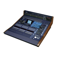
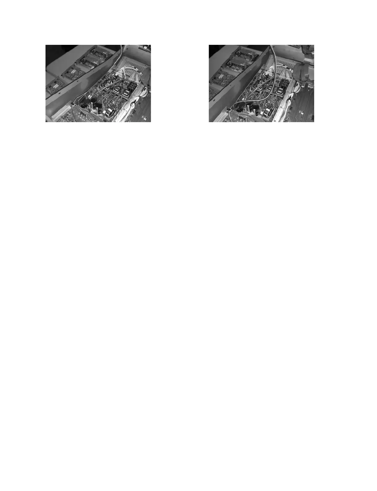
Photo.6 Photo.7
10. OPT Circuit Board
(Time required: About 20 minutes)
10-1. Remove the SP2000. (See procedure 1.)
10-2. Remove the MB2000. (See procedure 2.)
10-3. Fasten the control panel assembly. (See procedure 3.)
10-4. Fasten the rear assembly U. (See procedure 4.)
10-5. Remove the six (6) screws marked [270A]. The OPT
circuit board can then be removed. (Fig.3)
11. DA1 and JK1 Circuit Boards
(Time required: About 25 minutes each)
11-1. Remove the SP2000. (See procedure 1.)
11-2. Remove the MB2000. (See procedure 2.)
11-3. Fasten the control panel assembly. (See procedure 3.)
11-4. Fasten the rear assembly U. (See procedure 4.)
11-5. Remove the six (6) screws marked [235], the thirteen
(13) screws marked [370], the six (6) screws marked
[380] and the four (4) screws marked [400]. The
P.C.B. holder and the duct can then be removed with
the DA1 and JK1 circuit boards. (Fig.4, 5)
11-6. DA1 Circuit Board:
Remove the three (3) screws marked [240]. The DA1
circuit board can then be removed from P.C.B. holder.
(Fig.5)
11-7. JK1 Circuit Board:
Remove the DA1 circuit board. (See procedure 11-6.)
Remove the three (3) screws marked [365]. The JK1
circuit board can then be removed from P.C.B. holder.
(Fig.4)
12. JK2 Circuit Board
(Time required: About 25 minutes)
12-1. Remove the SP2000. (See procedure 1.)
12-2. Remove the MB2000. (See procedure 2.)
12-3. Fasten the control panel assembly. (See procedure 3.)
12-4. Fasten the rear assembly U. (See procedure 4.)
12-5. Remove the P.C.B. holder and the duct with the DA1
and JK1 circuit boards. (See procedure 11-5.)
12-6. Remove the three (3) screws marked [345], the two
(2) screws marked [350A], the two (2) screws marked
[355], the two (2) screws marked [C], the two (2)
screws marked [D], the two (2) screws marked [E]
and the two (2) screws marked [F]. The JK2 circuit
board can then be removed. (Fig.3, 5)
<OK> <NG>
 Loading...