45
DM2000
Fan guard
[130] x 2
[130] x 2
[430] [220A]
Spacer
[310] x 7
Shield box
DC fan motor
[345]
[270A]
Power supply unit
Fan guide
[290A] x 6
[255] x 8
BRG DSP
OPT
JK2
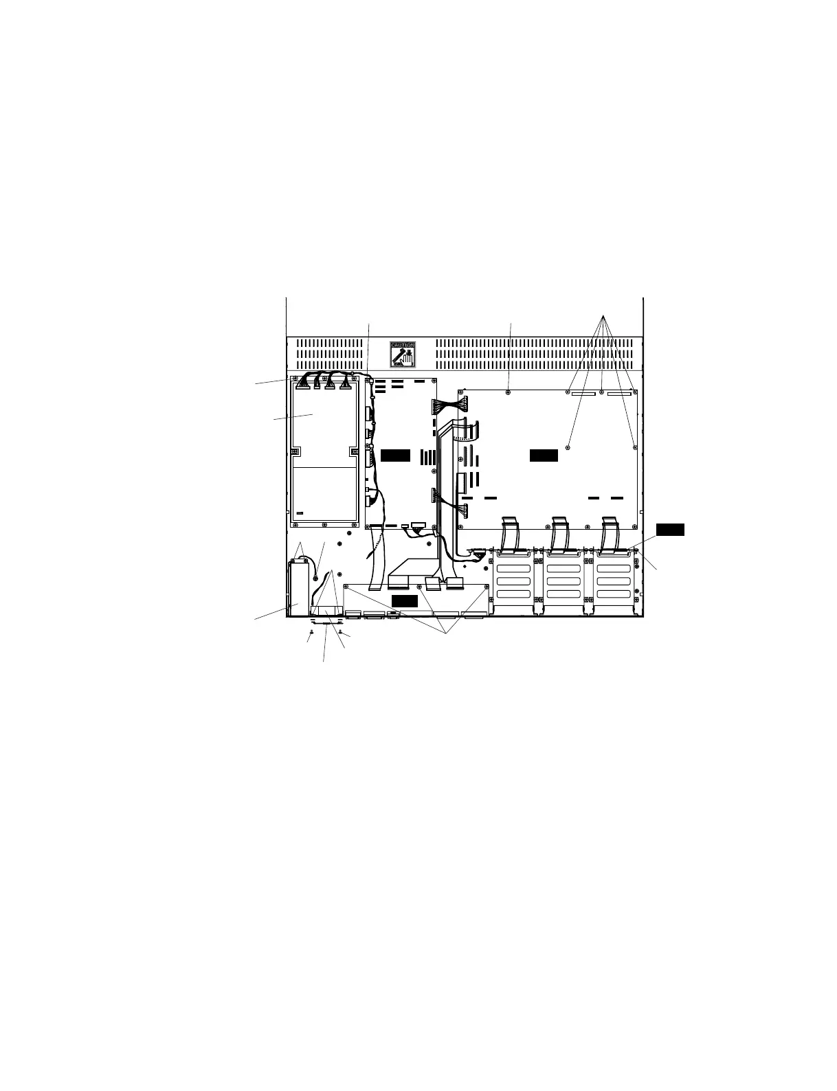
<Top view>
Fig.3
[130]: Pan Head Screw SP 4.0X20 MFZN2BL (VB671600)
[220A]:Bind Head Tapping Screw-S 4.0X8 MFZN2BL (VI693100)
[255]: Bind Head Tapping Screw-B 3.0X8 MFZN2BL (EP600190)
[270A]:Bind Head Screw 4.0X8 SP MFZN2Y (VZ538000)
[290A]:Bind Head Tapping Screw-B 3.0X8 MFZN2BL (EP600190)
[310]: Bind Head Tapping Screw-B 3.0X8 MFZN2BL (EP600190)
[345]: Bind Head Tapping Screw-B 3.0X8 MFZN2BL (EP600190)
[430]: Bind Head Tapping Screw-B 3.0X8 MFZN2BL (EP600190)
13. DC Fan Motor
(Time required: About 20 minutes)
13-1. Remove the SP2000. (See procedure 1.)
13-2. Remove the MB2000. (See procedure 2.)
13-3. Fasten the control panel assembly. (See procedure 3.)
13-4. Fasten the rear assembly U. (See procedure 4.)
13-5. Remove the four (4) screws marked [130]. The DC
fan motor, the two (2) fan guides, the fan guard and
the two (2) toothed lock washers can then be
removed. (Fig.3)
14. AC Inlet Assembly and SW Circuit Board
(Time required: About 25 minutes each)
14-1. Remove the SP2000. (See procedure 1.)
14-2. Remove the MB2000. (See procedure 2.)
14-3. Fasten the control panel assembly. (See procedure 3.)
14-4. Fasten the rear assembly U. (See procedure 4.)
14-5. Remove the screw marked [220A], the two (2) screws
marked [225] and the two (2) screws marked [430].
The shield box can then be removed with the AC inlet
assembly and the SW circuit board. (Fig.3, 5, 6)
14-6. Remove the six (6) screws marked [205A]. The shield
box cover can then be removed from the shield box. (Fig.6)
 Loading...