Do you have a question about the Yamaha DX27 and is the answer not in the manual?
Details of ROM version updates, addressing functional problems and test program changes.
Crucial safety warnings, handling instructions, and service advisories for safe operation and maintenance.
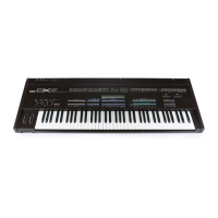
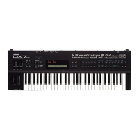
Detailed technical specifications for the DX27 synthesizer, including hardware and features.
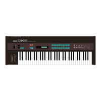
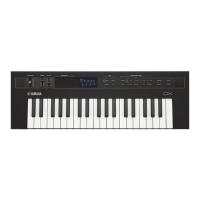
Detailed technical specifications for the DX100 synthesizer, including hardware and features.
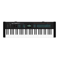
Illustration and labeling of the DX27's front panel controls and indicators.
Illustration and labeling of the DX27's rear panel connectors and ports.
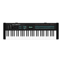
Illustration and labeling of the DX100's front panel controls and indicators.
Illustration and labeling of the DX100's rear panel connectors and ports.
Explanation of the main clock signal generation and division process.
Description of the sub-clock circuit used for MIDI clock generation.
Details on the reset signal generation and its impact on system initialization.
Information on CPU operation, ROM, and RAM allocation and addressing schemes.
Mapping of CPU addresses to internal registers, ports, ROM, and RAM locations.
Explanation of the Analog-to-Digital converter circuit's operational principles.
Description of the FM sound generator and DAC responsible for audio output.
Details on the headphone amplification circuit and its specifications.
Explanation of the circuit responsible for scanning panel and keyboard switches.
Description of the MIDI interface connections, standards, and functionality.
Details on the cassette interface operation for data transfer and storage.
Explanation of how power is supplied, regulated, and distributed within the unit.
Functionality of the power LED in indicating low battery voltage on the DX100 model.
Defines the conditions and message types for MIDI data transmission from the synthesizer.
Details channel voice messages, control changes, and program changes in MIDI transmission.
Specifics on Key ON/OFF, Note Number, Velocity, and Pitch Bend MIDI messages.
Information on Active Sensing messages and their timing within MIDI communication.
Details on Parameter Change, 1 Voice Bulk, and 32 Voice Bulk MIDI messages for data transfer.
Defines the conditions and message types for MIDI data reception by the synthesizer.
Details channel voice messages, control changes, and program changes received via MIDI.
How Parameter Change, Bulk Data, and Dump Requests are received and processed via MIDI.
Parameters for Voice Data (VMEM format) including rates, levels, LFO, and modulation settings.
Comprehensive list of voice parameters, their LCD display names, and data ranges for editing.
List of function parameters, their LCD display names, and data ranges for operational control.
Details on default channel, mode settings, and message handling for DX27 MIDI communication.
MIDI message specifics for note, velocity, pitch bend, control, and program change on DX27.
MIDI implementation for system exclusive, real-time, and auxiliary messages on DX27.
Details on default channel, mode settings, and message handling for DX100 MIDI communication.
MIDI message specifics for note, velocity, pitch bend, control, and program change on DX100.
MIDI implementation for system exclusive, real-time, and auxiliary messages on DX100.
Identification of the DM circuit board part numbers for DX27 and DX100 models.
Identification of the LCD circuit board part number specifically for the DX100 model.
Identification of the DX27 PNA and PNB circuit boards with their respective part numbers.
Identification of the DX100 PNA and PNB circuit boards with their respective part numbers.
A parts breakdown and list for the overall assembly of the DX27 model, including major components.
Parts list for DX27 upper/lower cases, wheels, buttons, and various internal electronic parts.
Parts list for DX27 circuit boards, connectors, and associated electronic components like resistors and potentiometers.
Detailed parts list for the DX27 keyboard frame assembly and its individual components like keys and springs.
Exploded view and numbered parts list for the DX100 overall assembly, showing component relationships.
Detailed parts for the DX27 wheel assembly, including springs, angles, and potentiometers.
Detailed parts for the DX100 wheel unit, including springs, angles, and connectors.
Identification of DM circuit boards and associated electronic components like resistors, ICs, capacitors, and diodes.
Parts list for various connector housings, circuit boards, and electronic components for DX27/DX100 models.
Pin function details for the YM2164 OPP integrated circuit, essential for circuit analysis.
Pin function details for the YM3014 DAC integrated circuit, crucial for understanding audio output circuitry.
Instructions for data backup and test program preparation, including necessary connections.
Steps to enter different test modes and their specific operational functions.
Procedure for testing output levels and RAM backup battery voltage integrity.
Automated checks for RAM, Cassette, and MIDI interface functionality.
Procedure for verifying the functionality of the LCD display by flashing patterns.
Testing analog-to-digital conversion by checking controls like Pitch Bend and Volume.
Procedure for testing the foot switch input detection circuit's responsiveness.
Steps to test each key contact by depressing and releasing them sequentially.
Procedure for adjusting and verifying the LCD contrast settings for optimal readability.
Test for the DX100's low battery warning indicator functionality.
Procedure to verify the functionality of all panel switches by pressing them according to prompts.
Overview of input controls, display, and parameter selection elements in the block diagram.
Diagram of MIDI, Cassette interface, and CPU connections and their interaction.
Block flow illustrating ROM, RAM, Tone Generator, D/A converter, and audio output paths.
Illustration of the clock generator and power supply circuits within the synthesizer's architecture.
Flowchart and step-by-step instructions for disassembling the DX27 model for servicing.
Flowchart and step-by-step instructions for disassembling the DX100 model for servicing.
| Synthesis Type | FM |
|---|---|
| Polyphony | 8 voices |
| Number of Operators | 4 |
| Keyboard | 61 keys |
| MIDI | Yes |
| Year Released | 1985 |
| Timbrality | Monotimbral |
| LFO | 1 |
| Oscillators | 4 operators |
| Memory | 192 patches |
| Control | Pitch bend |
| Outputs | Headphones |