2-2
E
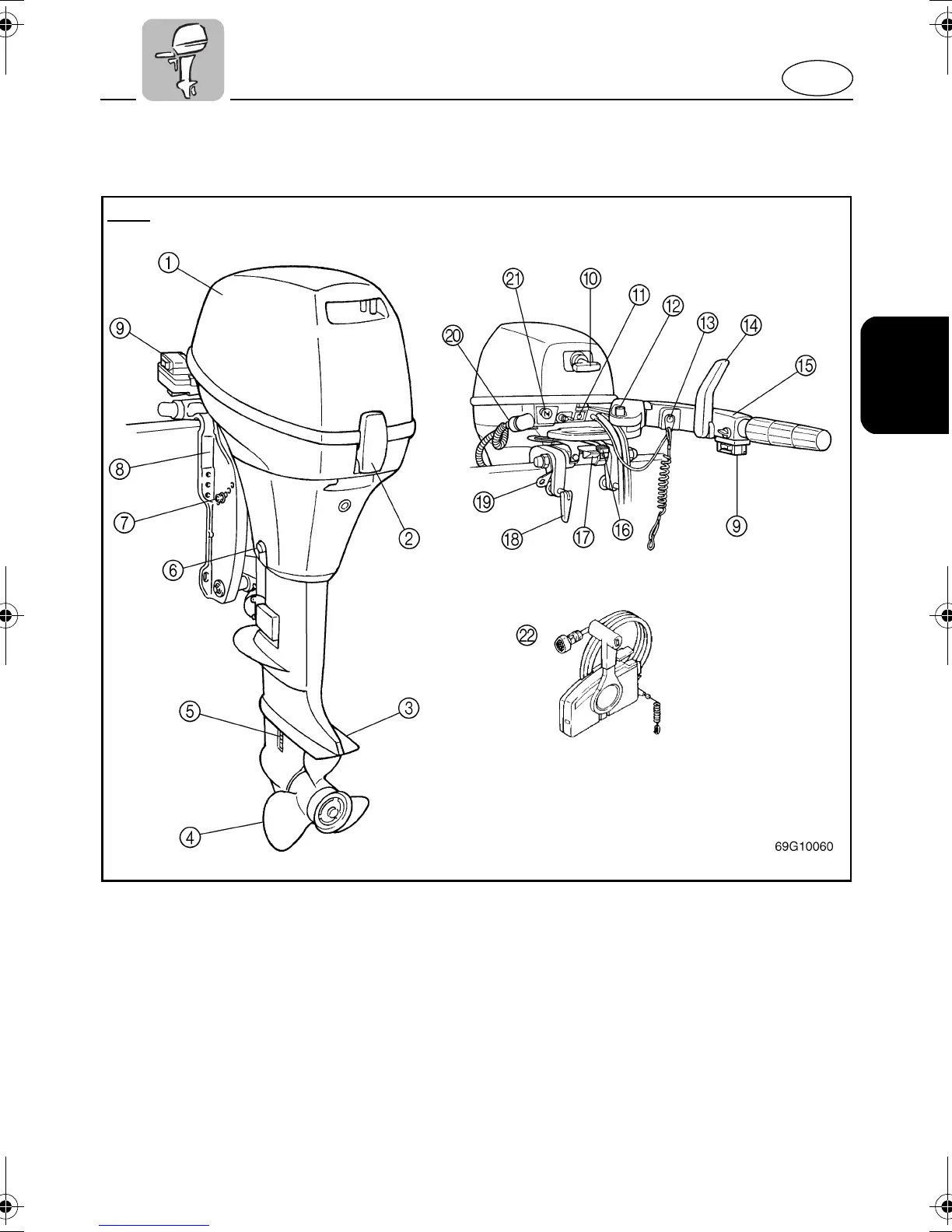
1
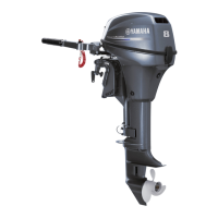
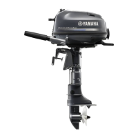
Top cowling
2
Top cowling lock lever
3
Anti-cavitation plate
4
Propeller
5
Cooling water inlet
6
Oil drain bolt
7
Trim angle adjusting rod
8
Clamp bracket
*
9
Power tilt switch
*
0
Recoil starter handle
A
Warning indicator
*
B
Starter button
*
C
Engine stop layard switch/
Engine stop button
*
D
Gear shift lever
*
E
Tiller handle
*
F
Steering friction adjusting lever
*
G
Tilt lock lever
H
Clamp screw
I
Rope attachment
J
Flushing device
K
Choke knob
*
L
Remote control box
* May not be exactly as shown; also may not be in-
cluded as standard equipment on all models.
T8A
U68T14.book Page 2 Monday, April 1, 2002 4:32 PM