Do you have a question about the Yamaha FG411SCE and is the answer not in the manual?
Provides crucial advice on safe servicing, potential hazards, and proper handling of electronic components.
Details the presence of lead in solder and other chemicals, with strict warnings against ingestion and skin contact.
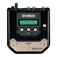
Details the layout and function of the main control knobs and switches on the guitar's electronics.
Explains the operation of the LOW, MID, HIGH, and AMF equalizer controls for tone shaping.
Describes the battery indicator, mute switch, and volume control for operational feedback and control.
Diagrams and part numbers for the FG model, showing pickup, jack, preamp, and battery placement.
Diagrams and part numbers for the APX model, detailing component installation locations.
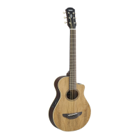
Illustrates the parts arrangement for the LW model, including pickup, jack, preamp, and battery.
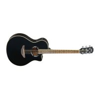
Shows the component placement for the APX model of System 34.
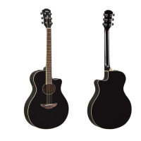
Visual representation of the overall assembly of the System 33 (FG) guitar, showing numbered parts.
Diagram of the overall assembly for the System 33 (APX) model, illustrating component placement.
Visual guide to the overall assembly of the System 34 (LW) guitar, detailing component layout.
Diagram illustrating the overall assembly for the System 34 (APX) model, showing component positions.
Details the main ICs, LED, and capacitor types used on the T circuit board.
Lists carbon resistors, slide variable resistors, and rotary potentiometers with their values and functions.
Identifies the push switch for mute function and base post connectors for pickup and output.
| Body Shape | Dreadnought |
|---|---|
| Back Material | Mahogany |
| Side Material | Mahogany |
| Neck Material | Nato |
| Fingerboard Material | Rosewood |
| Scale Length | 25.5 inches |
| Nut Width | 1.69 inches |
| Bridge Material | Rosewood |
| Fingerboard Radius | 15.75 inches |
| Number of Frets | 20 |
| Color Options | Natural |
| Finish | Gloss |
| Top Material | Spruce |
| Controls | Volume |