Do you have a question about the Yamaha G100-410 and is the answer not in the manual?
Technical output power rating of the amplifier in RMS with specified THD.
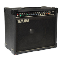
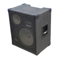
Details of the speaker type and size used in each model.
Input signal level required for a specific output, measured in dBm or mV.
Electrical resistance at the input terminals, measured in ohms.
Signal level and line type for the record output.
Specifies the noise floor level relative to volume control settings.
Type of reverb unit used in the amplifier.
Parameters for the tremolo effect, including depth and speed.
Description of the available input types and their gain characteristics.
List of continuously variable controls on the amplifier.
Functions controlled by external footswitches.
Voltage, frequency, and power consumption specifications.
Physical size measurements of the amplifier.
The total weight of the amplifier.
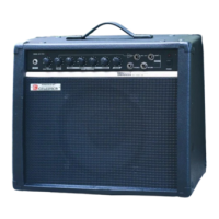
Description of the exterior casing and construction.
Steps to safely remove the main amplifier circuit board.
Procedure for detaching the main amplifier chassis from the cabinet.
Specifications for external test equipment used for adjustments.
Procedure to adjust the output waveform for symmetry.
Steps to set the DC bias voltage of the amplifier.
Procedure to set the quiescent current of the amplifier.
Checks the amplifier's amplification factor at specific input levels.
Measures the total harmonic distortion at rated output power.
Evaluates the amplifier's output level across a range of frequencies.
Measures the amplifier's inherent noise floor under various conditions.
| Type | Guitar Amplifier |
|---|---|
| Power Output | 100 Watts |
| Channels | 2 |
| Reverb | Yes |
| Inputs | 1 x Instrument |
| Amplifier Type | Solid State |
| Speaker Size | 10 inches |
| Controls | Treble, Middle, Bass |
| EQ Controls | Treble, Middle, Bass |