EasyManua.ls Logo

Yamaha portatone psr 2100 User Manual

Yamaha portatone psr 2100
111 pages
To Next Page IconTo Next Page
Page #1 background imageLoading...
Page #1 background image
CONTENTS(目次)
SPECIFICATIONS(総合仕様)············································ 3/4
PANEL LAYOUT(パネルレイアウト)···································· 6
CIRCUIT BOARD LAYOUT(ユニットレイアウト)················ 8
DISASSEMBLY PROCEDURE(分解手順)·························· 10
LSI PIN DESCRIPTIONLSI 端子機能表)··························· 17
IC BLOCK DIAGRAMIC ブロック図)································ 24
CIRCUIT BOARDS(シート基板図)····································· 25
TEST PROGRAM(テストプログラム)··························· 41/44
SYSTEM RESET(システムリセット)································· 48
MIDI IMPLEMENTATION CHART·········································· 49
MIDI DATA FORMAT ······························································ 50
PARTS LIST
BLOCK DIAGRAM(ブロックダイアグラム)
OVERALL CIRCUIT DIAGRAM(総回路図)
HAMAMATSU, JAPAN
Copyright (c) Yamaha Corporation. All rights reserved. PDF-K9271 '03.04
PK
001701
SERVICE MANUAL
PSR-1100: 20030421-120000
PSR-2100: 20030421-160000
PSR-1100
PSR-2100
Question and Answer IconNeed help?

Do you have a question about the Yamaha portatone psr 2100 and is the answer not in the manual?

Yamaha portatone psr 2100 Specifications

General IconGeneral
BrandYamaha
Modelportatone psr 2100
CategoryElectronic Keyboard
LanguageEnglish

Summary

IMPORTANT OPERATIONAL NOTICES AND WARNINGS

Chemical Content Safety Advisory

Advisory regarding lead solder and chemical content in product components for user safety.

PRODUCT SPECIFICATIONS OVERVIEW

PANEL LAYOUT AND CONTROL IDENTIFICATION

Control Panel Button and Dial Descriptions

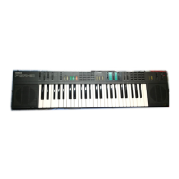
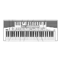
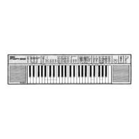
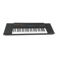
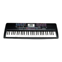
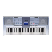
Identification and function of buttons, dials, and switches on the control panel.

CIRCUIT BOARD LAYOUT DIAGRAMS

Component Placement on Circuit Boards

Diagrams illustrating the physical placement of components on main circuit boards.

PRODUCT DISASSEMBLY AND ASSEMBLY

Step-by-Step Disassembly Instructions

Detailed instructions for disassembling the lower case and accessing internal circuit boards.

SPECIFIC CIRCUIT BOARD ACCESS

VR, ENC, PN1-PN4, and LCD Board Handling

Procedures for removing and installing VR, ENC, PN1-PN4, and LCD circuit boards.

LSI PIN DESCRIPTIONS

Key Integrated Circuit Pinout Details

Detailed pin descriptions for major ICs including CPUs, ADC, DAC, LCDC, and Tone Generators.

INTEGRATED CIRCUIT BLOCK DIAGRAMS

Logic Gate and IC Function Diagrams

Illustrations of logic gates and integrated circuit block diagrams for key components.

CIRCUIT BOARD DIAGRAM INDEX

PSR-1100 CIRCUIT BOARD DIAGRAMS

DM Circuit Board Layout (PSR-1100)

Diagram showing component placement on the DM circuit board for PSR-1100.

CIRCUIT BOARD DIAGRAMS (PN, ENC)

PN1, PN2, and ENC Circuit Board Layouts

Diagrams showing component placement on PN1, PN2, and ENC circuit boards.

CIRCUIT BOARD DIAGRAMS (ENC)

ENC Circuit Board Layout

Diagram showing component placement on the ENC circuit board.

CIRCUIT BOARD DIAGRAMS (PN, PB)

PN3, PN4, PB1, and PB2 Circuit Board Layouts

Diagrams showing component placement on PN3, PN4, PB1, and PB2 circuit boards.

CIRCUIT BOARD DIAGRAMS (MOD)

MOD Circuit Board Layout (PSR-2100 only)

Diagram showing component placement on the MOD circuit board for PSR-2100.

CIRCUIT BOARD DIAGRAMS (AM, VR)

AM and VR Circuit Board Layouts

Diagrams showing component placement on AM and VR circuit boards.

TEST PROGRAM OPERATION GUIDE

Test Program Preparation and Execution

Instructions for preparing and running the built-in diagnostic test program.

SYSTEM RESET PROCEDURES

Restoring Factory Settings and Data

Instructions for resetting system setup, MIDI, user effects, and music finder to factory defaults.

MIDI IMPLEMENTATION CHART

MIDI DATA FORMAT EXPLANATION

MIDI PARAMETER CHANGE TABLES

XG System and System Information Parameters

Tables detailing MIDI parameter changes for XG System and System Information.

MIDI PARAMETER CHANGE TABLE: EFFECT 1

MIDI PARAMETER CHANGE TABLE: VARIATION

Variation Effect Parameter Details

Details on MIDI control for variation effects, including parameter ranges.

MIDI PARAMETER CHANGE TABLE: MULTI EQ / EFFECT 2

Multi EQ and Insertion Effect Parameters

MIDI control parameters for Multi EQ and Insertion Effects.

MIDI PARAMETER CHANGE TABLE: SPECIAL EFFECT

MIDI PARAMETER CHANGE TABLE: MULTI PART

MIDI PARAMETER CHANGE TABLE: DRUM SETUP

SYSTEM EXCLUSIVE MESSAGES GUIDE

Universal Realtime and Non-Realtime Message Formats

Format and function of universal real-time and non-real-time system exclusive messages.

PARTS LIST AND IMPORTANT WARNINGS

Component Replacement Warnings and Notes

Warnings about special characteristic components and notes on parts list conventions.

OVERALL ASSEMBLY DIAGRAM

UPPER CASE ASSEMBLY DIAGRAM

KEYBOARD ASSEMBLY DIAGRAM

LOWER CASE ASSEMBLY DIAGRAM

PSR-1100 ELECTRICAL PARTS LIST

PSR-2100 ELECTRICAL PARTS LIST

PSR-1100 BLOCK DIAGRAM

PSR-2100 BLOCK DIAGRAM

PSR-1100 OVERALL CIRCUIT DIAGRAM

PSR-2100 OVERALL CIRCUIT DIAGRAM

PSR-1100/PSR-2100 OVERALL CIRCUIT DIAGRAM (DM, PN, ENC, PB, MOD)

PSR-1100/PSR-2100 OVERALL CIRCUIT DIAGRAM (AM, VR, HP, SW, MKS5F)

Related product manuals