EasyManua.ls Logo

Yamaha SILENT Piano SD Series User Manual

Yamaha SILENT Piano SD Series
51 pages
To Next Page IconTo Next Page
Page #1 background imageLoading...
Page #1 background image
CONTENTS
SPECIFICATIONS ................................. 3
SWITCH BOX & PEDAL
................................... 4
CIRCUIT BOARD LAYOUT ... 5
DISASSEMBLY PROCEDURE ............... 6
LSI PIN DESCRIPTION ................ 13
IC BLOCK DIAGRAM .................... 15
CIRCUIT BOARDS ......................... 16
TEST MODE, ADJUSTMENT
....................................... 20/22
CHECKING VERSIONS AND TYPES
............. 24/26
SWITCH BOX SELF-TEST MODE
.......................... 28
PARTS LIST
BLOCK DIAGRAM, UNIT COMPARISON
WIRING
OVERALL CIRCUIT DIAGRAM
SERVICE MANUAL
PP
008610
SILENT SD SERIES
b1-Silent / JU109-Silent
(C109)
b2-Silent / JX113T-Silent
(C113T)
Copyright (c) Yamaha Corporation. All rights reserved. PDF ’06.08
HAMAMATSU, JAPAN
b1-Silent/JU109-Silent (C109) b2-Silent/JX113T-Silent (C113T)
(総合仕様)
(スイッチボックスとペダル)
(ユニットレイアウト)
(分解手順)
(LSI端子機能表)
(ICブロック図)
(シート基板図)
(テストモード、調整)
(バージョン、プログラム種別の確認)
(スイッチボックス自己診断機能)
(ブロックダイアグラム、ユニット表)
(結線図)
(総回路図)
(目次)
Question and Answer IconNeed help?

Do you have a question about the Yamaha SILENT Piano SD Series and is the answer not in the manual?

Yamaha SILENT Piano SD Series Specifications

General IconGeneral
ModelSD Series
Keyboard88 keys
Hammer TypeVaries depending on the acoustic piano base model
Key SensorsNon
Pedal Type3 pedals (Damper, Sostenuto, Soft)
Soft/Sostenuto PedalYes
EffectsReverb, Brilliance
PlaybackYes
Internal MemoryNon
ConnectivityUSB to Host, Headphone jacks (x2)

Summary

IMPORTANT NOTICES AND SAFETY INFORMATION

General Service Precautions

Crucial safety rules for servicing the unit, emphasizing trained personnel and adherence to procedures.

Chemical Content Notice

Information on hazardous materials like lead in solder and potential chemicals in components.

Component Handling Warning

Warning about safe handling of specific components, especially regarding contact with solder and skin.

UK Power Adaptor Connection Guidance

Specific instructions for connecting the power adaptor plug and cord based on wire colors.

SPECIFICATIONS

General Specifications Overview

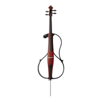
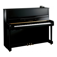
Details keyboard, pedal, voice, polyphony, sensors, controls, and terminals for the silent piano.

Supplied Accessories List

Lists items included with the product, such as AC adaptor, headphones, and manuals.

SWITCH BOX & PEDAL COMPONENTS

Front Panel Description

Explains controls and sockets on the front of the switch box unit.

Rear Panel Connections

Details connectors like PDL, KEY, and DC IN on the rear of the switch box unit.

CIRCUIT BOARD LAYOUT

b1-Silent/JU109-Silent (C109) Layouts

Visual guide to component placement for the switch box, key sensor, and pedal units.

DISASSEMBLY PROCEDURES

Switch Box Unit Removal

Step-by-step guide for removing the switch box unit from the piano.

CONTINUED DISASSEMBLY PROCEDURES

Switch Box Panel and Board Removal

Procedures for removing switch box front panel, upper case, and circuit boards.

CONTINUED DISASSEMBLY PROCEDURES

AM Circuit Board Removal

Procedure for removing the AM circuit board from the switch box chassis.

EXTERIOR AND KEYBOARD DISASSEMBLY

Front Panel Removal

Steps for removing the upper and lower front boards of the piano.

KEY STOPPER AND KEYBOARD REMOVAL

Keyboard and Key Stopper Removal

Procedures for removing the key stopper and all keyboards.

ELECTRICAL COMPONENT DISASSEMBLY

Key Sensor Unit and Pedal Unit Removal

Steps for removing the key sensor unit and pedal units.

LSI PIN DESCRIPTIONS

IC Pinout Details

Lists pins and functions for various integrated circuits used in the unit.

IC BLOCK DIAGRAMS

Integrated Circuit Block Diagrams

Visual representations of IC functions and connections.

CIRCUIT BOARD DIAGRAMS

AM Circuit Board Diagram

Visual layout of the AM circuit board with component locations.

CONTINUED CIRCUIT BOARD DIAGRAMS

DM Circuit Board Diagram

Visual layout of the DM circuit board with component locations.

CONTINUED CIRCUIT BOARD DIAGRAMS

DC-IN and KEY SENSOR Board Diagrams

Visual layouts for DC-IN and Key Sensor circuit boards with component locations.

TEST MODES AND ADJUSTMENTS

Key Sensor Adjustment (All Keys)

Procedure for measuring and adjusting all keys in the sensor system.

CONTINUED TEST MODES AND ADJUSTMENTS

Key Sensor Adjustment (One Key)

Procedure for measuring and adjusting individual keys.

Damper Pedal Sensor Adjustment

Procedure for adjusting the damper pedal sensor.

Sensor Test Mode Operation

How to start and perform the sensor test mode.

VERSION AND TYPE CHECKING

Sensor Information Verification

Method to check sensor type and version using piano sound notes.

CONTINUED VERSION AND TYPE CHECKING

Tone Generator Information Verification

Method to check tone generator type and version using piano sound notes.

SWITCH BOX SELF-TEST MODE

Self-Test Procedure Execution

Steps to initiate and perform the switch box self-test for diagnostics.

PARTS LIST

Parts List Overview and Notes

Introduction and important notes for the parts list, including abbreviations.

UNIT COMPARISON

Unit Part Number Cross-Reference

Table comparing different units and their corresponding part numbers.

ASSEMBLY DIAGRAMS

Overall Assembly Views

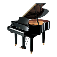
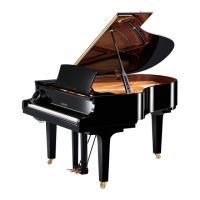
Diagrams showing the assembled piano for the C109 model.

CONTINUED ASSEMBLY DIAGRAMS

Key Sensor Assembly Diagrams

Detailed views of the key sensor assembly.

CONTINUED ASSEMBLY DIAGRAMS

Key Sensor Unit Diagrams

Diagrams of the key sensor unit.

CONTINUED ASSEMBLY DIAGRAMS

Switch Box Unit Diagrams

Detailed views of the switch box unit.

CONTINUED ASSEMBLY DIAGRAMS

Pedal Unit Diagrams

Detailed views of pedal units L and S.

ELECTRICAL PARTS LIST

Capacitors and Resistors

Lists various capacitors and resistors with their specifications.

ELECTRICAL PARTS LIST (CONTINUED)

ICs, Transistors, and Other Components

Lists integrated circuits, transistors, and other electronic parts.

SYSTEM OVERVIEW AND UNIT COMPARISON

System Block Diagram

High-level overview of system connections between major units.

Unit Comparison Table

Cross-reference of unit part numbers.

WIRING DIAGRAMS

Inter-Unit Wiring Connections

Detailed connection schematics between units like key sensor, DC-IN, and switch box.

OVERALL CIRCUIT DIAGRAMS

DM Circuit Diagram

Detailed circuit schematic for the DM board.

OVERALL CIRCUIT DIAGRAMS (CONTINUED)

AM, DC-IN, KEY SENSOR Circuit Diagrams

Detailed schematics for AM, DC-IN, and Key Sensor boards.

Related product manuals