Chapter 7 Reduction and Reversing Gear
2. Shifting Device
2.
Shifting
Device
4LHA Sen,
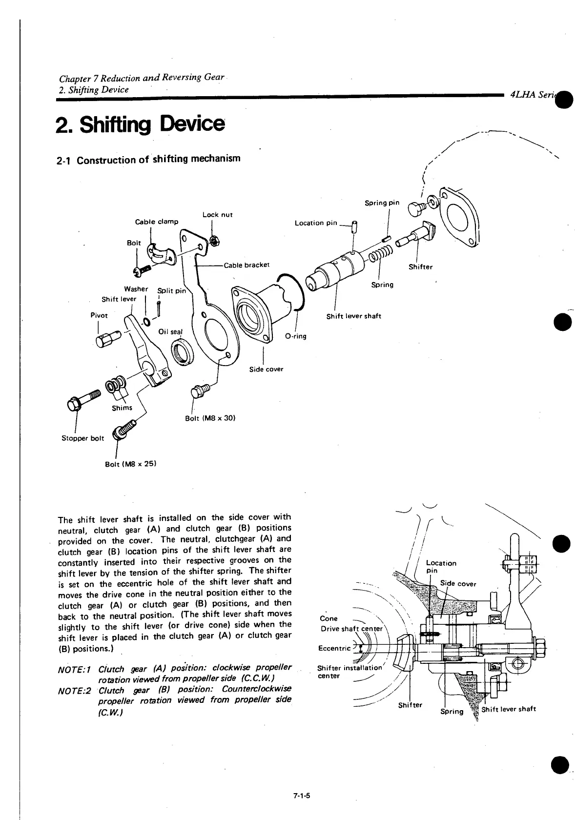
2-1
Construction
of
shifting
mechanism
Cable
clamp
Lock
nut
Bolt
Washer
S
p|j
t
Shift lever
Oil
seal
Side
cover
Bolt <M8 x 30)
Stopper
bolt
Bolt <M8 x 25)
The
shift
lever shaft is installed on the side cover
with
neutral, clutch gear (A) and clutch gear (B) positions
provided on the cover. The neutral, clutchgear (A) and
clutch gear (B) location pins of the
shift
lever shaft are
constantly inserted
into
their respective grooves on the
shift
lever by the tension of the shifter spring. The shifter
is
set on the eccentric hole of the
shift
lever shaft and
moves
the drive cone in the neutral position either to the
clutch gear (A) or clutch gear (B) positions, and then
back
to the neutral position. (The
shift
lever shaft moves
slightly to the
shift
lever (or drive cone) side when the
shift
lever is placed in the clutch gear (A) or clutch gear
(B) positions.)
NOTE:1 dutch gear (A) position: clockwise propeller
rotation viewed from propeller
side
(C.C.W.)
N0TE:2 Clutch gear (B) position: Counterclockwise
propeller rotation viewed from propeller side
(CW.)
Cone
—^ \ ^
Drive shaft center\
ift lever shaft
7-1-5

 Loading...