Parts List
A. Fence Assembly Pins (8)
B. M8 Washers (11)
C. M8 Lock Nuts (11)
D. Wheel Spacers (4)
E. Cotter Pins (5)
F. M16 Wheel Washers (4)
G. M8x20 Hex Head Bolts (6)
H. M8x40 Hex Head Bolts
I. M8x60 Hex Head Bolt (1)
J. M10 Washers (1)
Hardware List
Images are not to scale
A.
B.
D.
C.
E.
F.
G.
B.
H.
I.
J.
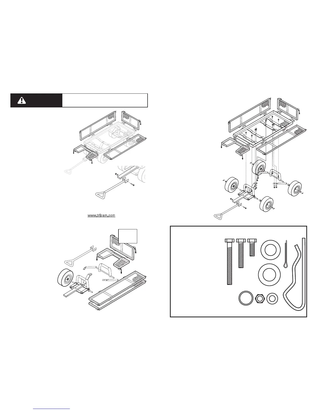
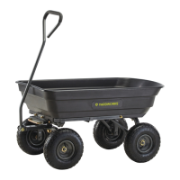
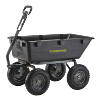
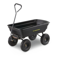
A. Bed (1)
B. Side Panels (2)
C. Front Panel (1)
D. Back Panel (1)
E. 10in (25.4cm) Wheels (4)
F. Rear Axle Support (1)
G. Left Rear Axle Brace (1)
H. Right Rear Axle Brace (1)
I. Front Axle Support (1)
J. Pull Handle (1)
Exploded Drawing for Assembly
B.
D.
C.
E.
F.
G.
H.
I.
A.
J.
B. Side Panels (2)
C. Front Panel (1)
D. Back Panel (1)
E. 10in (25.4cm) Wheels (4)
F. Rear Axle Support (1)
G. Left Rear Axle Brace (1)
H. Right Rear Axle Brace (1)
I. Front Axle Support (1)
J. Pull Handle (1)
K. Hardware Kit (1)
Replacement Parts List
B.
F.
G.
E.
For replacement parts, please visit us online at
w
ww.tricam.com
to complete the replacement parts submission form or call our
customer service department at 1-800-867-6763,
9 a.m. - 4 p.m., CST, Monday - Friday.
H.
I.
DO NOT EXCEED MAXIMUM OVERALL LOAD CAPACITY 400 LBS.
PERSON SHOULD NEVER RIDE IN THE UTILITY CART.
WEIGHT RATING IS BASED ON AN EVENLY DISTRIBUTED LOAD.
CAUTION
Step 7
Attach the front, back, left and right
fences using the fence assembly pins.
NOTE: Latch the fences in the upright
position using the lock handles.
Tighten the nuts on the lock handles to
allow for smooth operation while not
being overly tight.
Step 8
C.
D.
J.
K.
Attach the pull handle to the front axel
support using the M8x60 hex head bolt, M8
lock nut and M8 washer.