2.7 F: Options
268 YASKAWA TOEPYAIGA5002A GA500 Programming
F6-16
[Gateway Mode]
H5-01
[Drive Node
Address]
*1
H5-02
[Communication
Speed Selection]
H5-03
[Communication
Parity Selection]
H5-06
[Drive Transmit
Wait Time]
H5-09
[CE Detection
Time]
b1-01
[Frequency
Reference
Selection 1]
b1-02
[Run Command
Selection 1]
Drive 2
(Slave Drive)
0 02
*3 *4 *5
5 ms (Default)
*6
≥ 0.9 s
*7
2 [Memobus/Modbus
Communications]
*8
2 [Memobus/Modbus
Communications]
*8
Drive 3
(Slave Drive)
0 03
*3 *4 *5
5 ms (Default)
*6
≥ 0.9 s
*7
2 [Memobus/Modbus
Communications]
*8
2 [Memobus/Modbus
Communications]
*8
Drive 4
(Slave Drive)
0 04
*3 *4 *5
5 ms (Default)
*6
≥ 0.9 s
*7
2 [Memobus/Modbus
Communications]
*8
2 [Memobus/Modbus
Communications]
*8
*1 Re-energize the drive to apply the new settings.
*2 Specify the number of slave drives you will connect.
*3 Setting 0 will not let the drive respond to MEMOBUS/Modbus communications.
*4 Set a slave address that is different from other slave devices.
*5 Enter the same value that you use for the master drive.
*6 To correctly detect the response timeout, do not change the value of H5-06 from the default value.
*7 Set H5-09 ≥ 0.9. When H5-09 < 0.9, the drive will detect CE [Modbus Communication Error] before it detects a response timeout.
*8 On each slave drive, set b1-01 [Frequency Reference Selection 1] and b1-02 [Run Command Selection 1] to 2 [Memobus/Modbus
Communications].
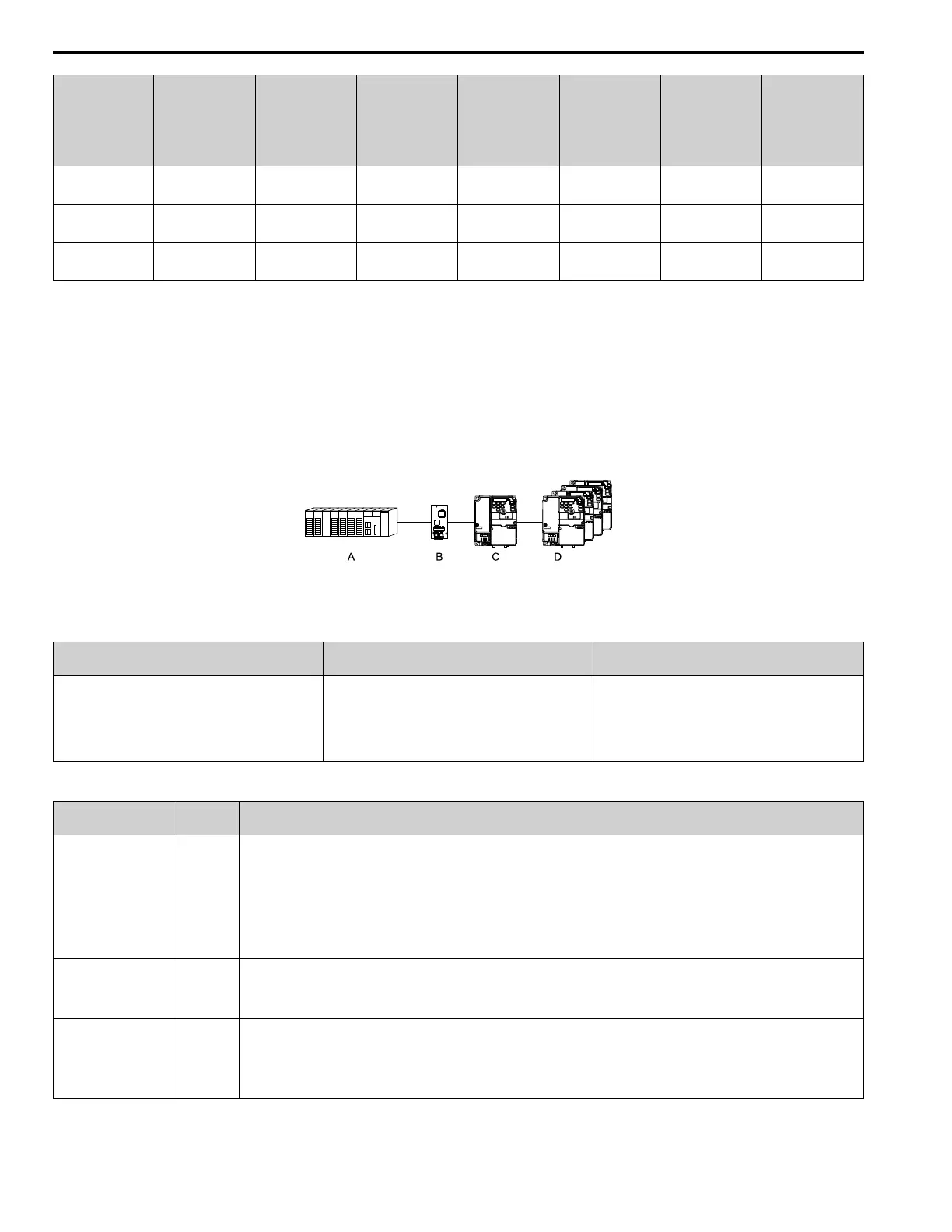
An Overview of Gateway Mode
When in gateway mode, the drive will operate as shown in Table 2.45.
A - Controller
B - Communication Option
C - Master Drive (Drive 0)
D - Slave Drives (Drives 1 to 4)
Table 2.45 Operation in Gateway Mode
Controller to Communication Option Communication Option to Master Drive (Drive 0)
Master Drive (Drive 0) to Slave Drives (Drives 1 to
4)
• The controller and card communicate in the format of
each field bus communications protocol.
• Drive 0 sends commands and monitors through normal
field bus communications.
• The special registers of Drive 0 use read and write to
send commands to and monitor Drives 1 to 4.
Field bus communication data is written to and read from
the special registers of Drive 0.
• Uses MEMOBUS communications.
• Drive 0 sends data from its special registers to Drives 1
to 4.
Operations at the Time of Communication Error
Communication Error
Error
Codes
Operation
From controller to
communication option
bUS
• Master drive
Detects bUS [Option Communication Error] and operates as specified by F6-01 [Communication Error Selection].
• Slave drive
Detects CE [Modbus Communication Error] and operates as specified by H5-04 [Communication Error Stop Method].
Note:
• After error detection, each drive can continue the operation specified by the last received command if the F6-01 and H5-04 settings
agree. Because the controller cannot stop the operation, you must supply a stopping method, for example an emergency stop switch.
• If you set H5-05 = 0 [Comm Fault Detection Selection = Disabled], the drive will not detect CE. The H5-04 setting does not have an
effect.
From communication
option to master drive
oFAxx
• Master drive
Detects oFAxx and coasts to stop.
• Slave drive
Detects hLCE [High Level Communication Errors] and coasts to stop.
From master drive to
slave drive
CE
The master drive stops communicating with the slave drive in these conditions: Reset the fault to restart communication.
The slave drive detects CE after H5-09 [CE Detection Time] is expired. Then it operates in as specified with H5-04 [Communication Error
Stop Method].
• A message error occurred in the send data from the slave drive 10 consecutive times.
• Response from the slave drive timed out 10 consecutive times.

 Loading...


