10 Drive Start-Up Procedure
40 YASKAWA TOEPC7106170VA GA800 600 V Drive Installation & Primary Operation
Table 10.6 Control Circuit Wire Gauges and Tightening Torques
Terminal Block Terminal Screw Size
Tightening
Torque
N∙m (in∙lb)
Bare Wire Crimp Ferrule
Recommended
Gauge
mm
2
(AWG)
Applicable
Gauge
mm
2
(AWG)
Recommended
Gauge
mm
2
(AWG)
Applicable
Gauge
mm
2
(AWG)
TB1 S1 - S8, SN, SC, SP
M3
0.5 - 0.6
(4.4 - 5.3)
0.75
(18)
• Stranded wire
0.2 - 1.0
(24 - 16)
• Solid wire
0.2 - 1.5
(24 - 16)
0.5
(20)
0.25 - 0.5
(24 - 20)
TB2 M1 - M6, MA, MB, MC
TB3
+V, AC, -V, A1, A2, A3, FM, AM,
AC, MP, RP, AC
TB4
E (G), SN, HC, H1, H2, PS, AC, D
+, D-
TB5 E (G) M3.5
0.5 - 1.0
(4.4 - 8.9)
0.5 - 2
(20 - 14)
1.25
(12)
- -
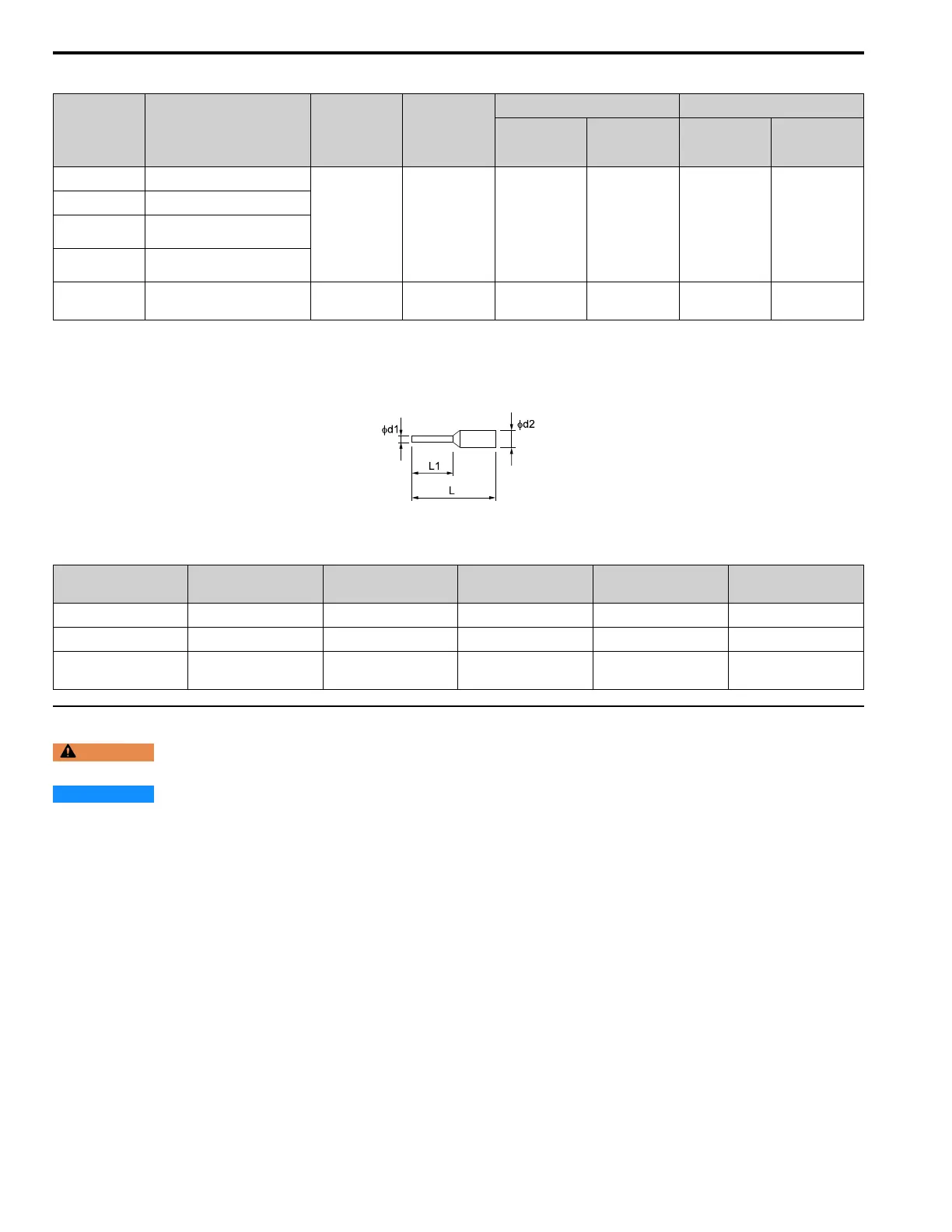
Crimp Ferrules
Attach an insulated sleeve when you use crimp ferrules. Refer to Table 10.7 for the recommended external
dimensions and model numbers of crimp ferrules.
Use the CRIMPFOX 6, a crimping tool made by PHOENIX CONTACT.
Figure 10.4 External Dimensions of Crimp Ferrules
Table 10.7 Crimp Ferrule Models and Sizes
Wire Gauge
mm
2
(AWG)
Model L (mm) L1 (mm) φd1 (mm) φd2 (mm)
0.25 (24) AI 0.25-8YE 12.5 8 0.8 2.0
0.34 (22) AI 0.34-8TQ 12.5 8 0.8 2.0
0.5 (20)
AI 0.5-8WH,
AI 0.5-8OG
14 8 1.1 2.5
◆ Wiring the Control Circuit Terminal
WARNING
Electrical Shock Hazard. Do not remove covers or touch circuit boards while the drive is energized. If you touch
the internal components of an energized drive, it can cause serious injury or death.
NOTICE
Do not let wire shields touch other signal lines or equipment. Insulate the wire shields with electrical tape or shrink
tubing. If you do not insulate the wire shields, it can cause a short circuit and damage the drive.
Note:
• Isolate control circuit wiring from main circuit wiring (terminals R/L1, S/L2, T/L3, B1, B2, U/T1, V/T2, W/T3, -, +1, +2, +3) and other
high-power wiring. If control circuit wiring is adjacent to main circuit wiring, it can cause incorrect operation of the drive and equipment
from electrical interference.
• Isolate wiring for contact output terminals MA, MB, MC and M1-M6 from other control circuit wiring. If contact output terminal wiring is
adjacent to other control circuit wiring, it can cause incorrect operation of the drive and equipment from electrical interference.
• Use a Class 2 power supply to connect external power to the control terminals. If the power supply for peripheral devices is incorrect, it can
cause a decrease in drive performance.
• Connect the shield of shielded cable to the applicable ground terminal. Incorrect equipment grounding can cause drive or equipment
malfunction from electrical interference.
Correctly ground the drive terminals and complete main circuit wiring before you wire the control circuit. Remove the
keypad and front cover.

 Loading...


