11 Drive Control, Duty Modes, and Programming
YASKAWA TOEPC7106170VA GA800 600 V Drive Installation & Primary Operation 47
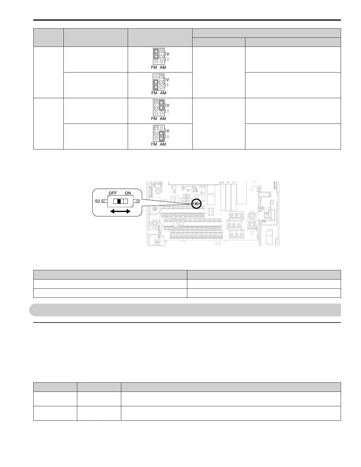
Terminal Types of Output Signals Jumper Switch S5
Parameter
No. Signal Level
FM
Voltage output
(Default)
H4-07
0: 0 V to 10 V
1: -10 V to +10 V
Current output 2: 4 mA to 20 mA
AM
Voltage output
(Default)
H4-08
0: 0 V to 10 V
1: -10 V to +10 V
Current output 2: 4 mA to 20 mA
■ Switch ON Termination Resistor for MEMOBUS/Modbus Communications
When the drive is the last slave in a MEMOBUS/Modbus communications, set DIP switch S2 to the ON position.
This drive has a built-in termination resistor for the RS-485 interface.
Figure 10.17 Location of DIP Switch S2
Table 10.10 MEMOBUS/Modbus Communications Termination Resistor Setting
DIP Switch S2 Description
ON The built-in termination resistor is ON.
OFF (Default) The built-in termination resistor is OFF.
11 Drive Control, Duty Modes, and Programming
◆ Selecting the Control Method
This section gives information about these basic control methods:
• V/f Control (V/f)
• Open Loop Vector Control (OLV)
Set the most applicable control method for your application. A1-02 [Control Method Selection] sets the drive
operation.
Control Method A1-02 Main Applications
V/f 0
• General variable-speed. Best method to operate more than one motor from one drive.
• When motor parameters are not available.
OLV
2
(Default)
• General variable-speed
• High precision and high speed response without speed feedback

 Loading...


