11 Drive Control, Duty Modes, and Programming
50 YASKAWA TOEPC7106170VA GA800 600 V Drive Installation & Primary Operation
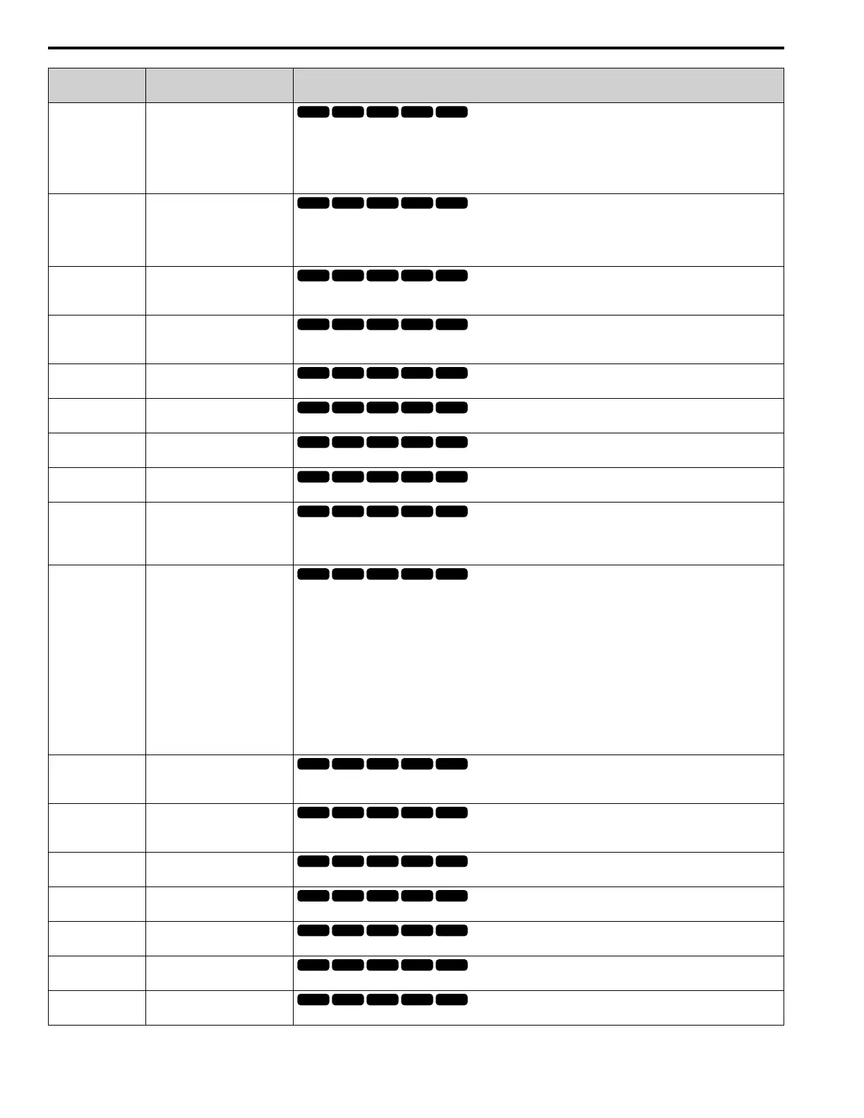
No.
(Hex.)
Name Description
b1-03
(0182)
Stopping Method Selection
Sets the method to stop the motor after removing a Run command or entering a Stop command.
0 : Ramp to Stop
1 : Coast to Stop
2 : DC Injection Braking to Stop
3 : Coast to Stop with Timer
b1-04
(0183)
Reverse Operation Selection
Sets the reverse operation function. Disable reverse operation in fan or pump applications where reverse rotation is
dangerous.
0 : Reverse Enabled
1 : Reverse Disabled
C1-01
(0200)
RUN
Acceleration Time 1
Sets the length of time to accelerate from zero to maximum output frequency.
C1-02
(0201)
RUN
Deceleration Time 1
Sets the length of time to decelerate from maximum output frequency to zero.
C2-01
(020B)
S-Curve Time @ Start of Accel
Sets the S-curve acceleration time at start.
C2-02
(020C)
S-Curve Time @ End of Accel
Sets the S-curve acceleration time at completion.
C2-03
(020D)
S-Curve Time @ Start of Decel
Sets the S-curve deceleration time at start.
C2-04
(020E)
S-Curve Time @ End of Decel
Sets the S-curve deceleration time at completion.
C6-01
(0223)
Normal / Heavy Duty Selection
Sets the drive duty rating.
0 : Heavy Duty Rating
1 : Normal Duty Rating
C6-02
(0224)
Carrier Frequency Selection
Sets the carrier frequency for the transistors in the drive.
1 : 2.0 kHz
2 : 5.0 kHz
3 : 8.0 kHz
4 : 10.0 kHz
5 : 12.5 kHz
6 : 15.0 kHz
7 : Swing PWM1 (Audible Sound 1)
8 : Swing PWM2 (Audible Sound 2)
9 : Swing PWM3 (Audible Sound 3)
A : Swing PWM4 (Audible Sound 4)
F : User Defined (C6-03 to C6-05)
d1-01 to d1-16
(0280 - 0291)
RUN
Reference 1 to 16
Sets the frequency reference in the units from o1-03 [Frequency Display Unit Selection].
d1-17
(0292)
RUN
Jog Reference
Sets the Jog frequency reference in the units from o1-03 [Frequency Display Unit Selection]. Set H1-xx = 6 [MFDI
Function Select = Jog Reference Selection] to use the Jog frequency reference.
d2-01
(0289)
Frequency Reference Upper Limit
Sets maximum limit for all frequency references. The maximum output frequency is 100%.
d2-02
(028A)
Frequency Reference Lower Limit
Sets minimum limit for all frequency references. The maximum output frequency is 100%.
E1-01
(0300)
Input AC Supply Voltage
Sets the drive input voltage.
E1-04
(0303)
Maximum Output Frequency
Sets the maximum output frequency for the V/f pattern.
E1-05
(0304)
Maximum Output Voltage
Sets the maximum output voltage for the V/f pattern.

 Loading...


