4.2 Powering Up the Drive
Review the following table before applying power.
Item to Check Description
Power supply voltage
200 V class: Three-phase/Single-phase 200 to 240 Vac 50/60 Hz
400 V class: Three-phase/Single-phase 380 to 480 Vac 50/60 Hz
600 V class: Three-phase/Single-phase 500 to 600 Vac 50/60 Hz
Properly wire the power supply input terminals (R/L1, S/L2, T/L3) for three-phase and (R/L1, S/L2) for single-phase.
Check for proper grounding of drive and motor.
Drive output terminals and
motor terminals
Properly wire drive output terminals U/T1, V/T2, and W/T3 with motor terminals U, V, and W.
Control circuit terminals Check control circuit terminal connections.
Drive control terminal status Open all control circuit terminals (off).
Status of the load and connected
machinery
Decouple the motor from the load.
u
Setting the Real Time Clock
When the drive is powered up for the first time, the time and date must be set. The HOA keypad will display the time and date
setup screen for 30 seconds. If a button is not pressed during this time, the display will clear and a “Clock Not Set” alarm will
flash. Pressing the F2 (Data) key will display the setting screen again.
n
Feedback Loss Wire Break Alarm
If there is no sensor wired to the drive, a “Feedback Loss – Wire Break” alarm will flash on the display after the 30-second
time and date screen has elapsed (not the “Clock Not Set” alarm). Providing the proper feedback device signal will clear the
Feedback Loss alarm. The “Clock Not Set” alarm will then flash.
The drive requires a feedback device (e.g., pressure transducer, flow meter, etc.) to perform automatic system regulation. Any
analog 0~10 V or 4-20 mA feedback device can be used in combination with the drive.
Note: The factory default setting for the drive is 4~20 mA feedback device connected to analog input A2.
n
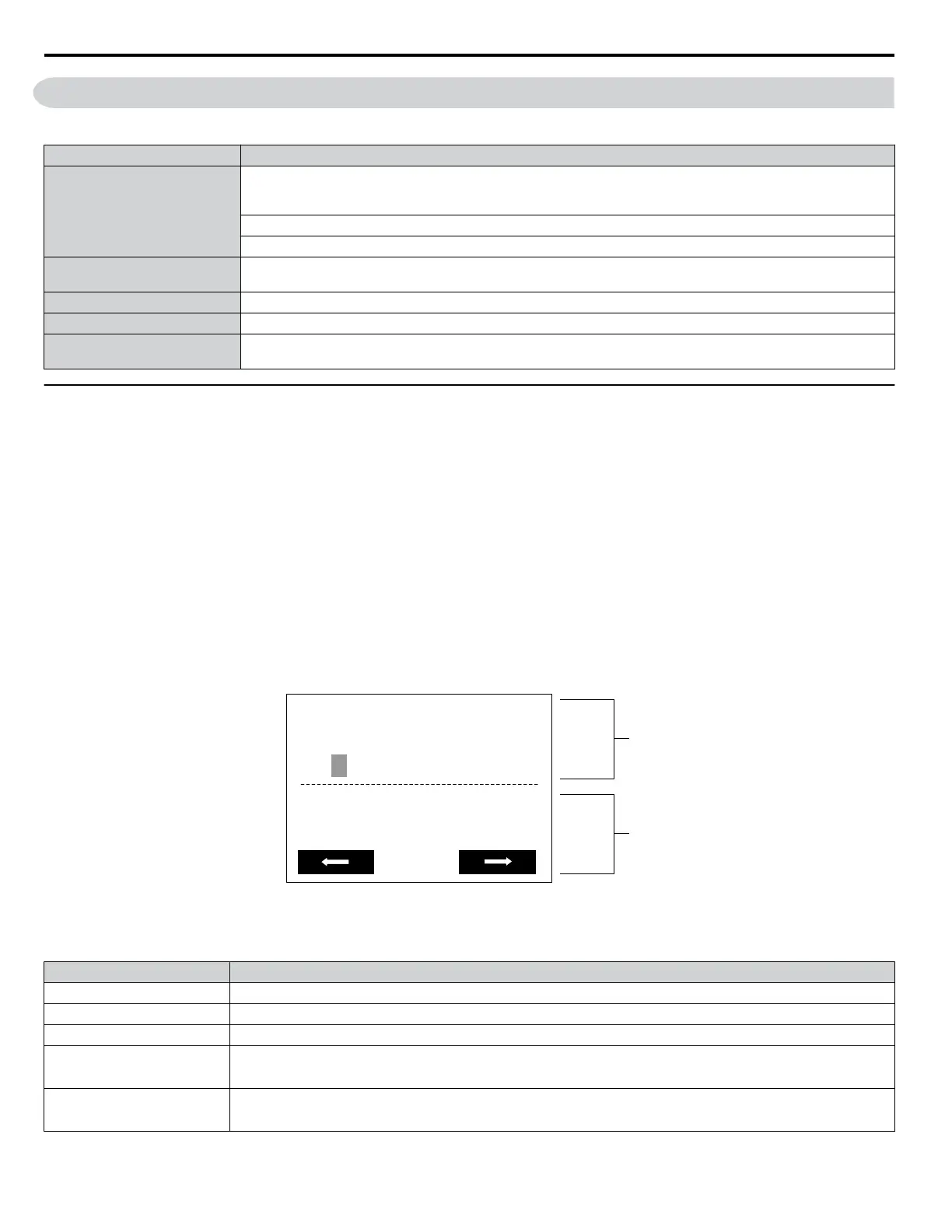
Real Time Clock Setting Display
Note: Setting the Real-Time Clock will clear a “TIM” alarm.
20 1 0/01/01 00:00
Second per month
+ 0 sec
YYYY/MM/DD HH:MM
FWD
A
B
A – Real Time Clock Setting Display
Set in 24-Hour Clock Time
B – Gain/Loss Adjustment Display
Figure 4.1 Real Time Clock Adjustment Display
Display Description
YYYY Set the year with the last two digits.
MM Set the month with two digits.
DD Set the day with two digits.
HH:MM
Set the hours and minutes, with two digits for each.
Note: Set in 24-hour clock time. After initial setup, the time will display in 12-hour clock time.
Second per month
Set the gain or loss in seconds per month.
Note: This does not need to be set for the RTC to function properly.
4.2 Powering Up the Drive
108
YASKAWA TOEP YAIP1W 01A YASKAWA AC Drive - iQpump1000 Quick Start Guide

 Loading...


