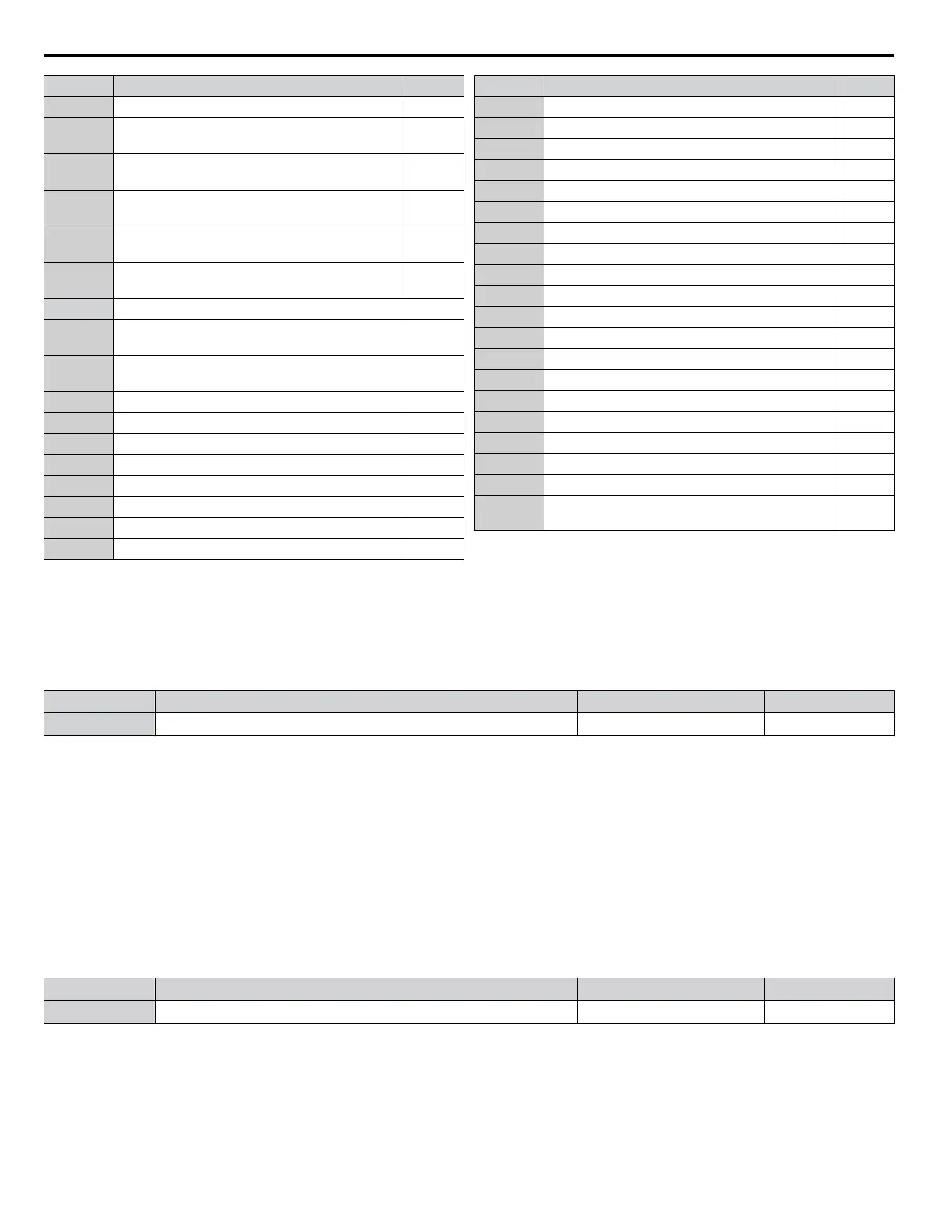
Setting Function Page
50 Waiting to Run –
51
Sequence timer 1
SeqTimer Disable
–
52
Sequence timer 2
SeqTimer Cancel
–
53
Sequence timer 3
Sequence timer 3
–
54
Sequence timer 4
Sequence Timer 4
–
58
Underload detection
UL6
–
60 Internal cooling fan alarm –
71
Secondary PI Feedback Low
PI2 Feedback Low
–
72
Secondary PI Feedback High
PI2 FeedbackHigh
–
73 Low City Press –
80 Pump 2 Control –
81 Pump 3 Control –
82 Pump 4 Control –
83 Pump 5 Control –
84 Pump 6 Control –
89 Output 1 Limit –
8B Lube Pump –
Setting Function Page
91 Pump Fault –
92 Transducer Loss –
93 Setptoint Not Met –
94 Loss of Prime –
95 Volute Thermostat Fault
96 High Feedback –
97 Low Feedback –
98 Low Flow –
99 Accum Level –
9A High Flow –
9B Low Water Level –
9C Low Suction –
9D High Suction –
A2 Sleep Active –
A3 Start Delay –
A4 Pre-Charge –
A5 Anti-Jam Active –
A9 Thrust Mode –
AA Utility Start Delay –
100 to
1AA
Function 0 to AA with inverse output –
Setting 30: During Torque Limit
The output closes when the motor is operating at the torque limit specified by the L7-oo parameters or an analog input. This
setting can only be used in OLV control mode.
n
H3-01: Terminal A1 Signal Level Selection
Selects the input signal level for analog input A1.
No. Name Setting Range Default
H3-01 Terminal A1 Signal Level Selection 0 to 3 0
Setting 0: 0 to 10 Vdc
The input level is 0 to 10 Vdc. The minimum input level is limited to 0%, so that a negative input signal due to gain and bias
settings will be read as 0%.
Setting 1: 0 to 10 Vdc Bipolar
The input level is -10 to 10 Vdc. If the resulting voltage is negative after being adjusted by gain and bias settings, then the
motor will rotate in reverse.
Setting 2: 4 to 20 mA
Setting 3: 0 to 20 mA
n
H3-02: Terminal A1 Function Selection
Selects the input signal level for analog input A3.
No. Name Setting Range Default
H3-02 Terminal A1 Function Selection 0 to 32 0
n
H3-03, H3-04: Terminal A1 Gain and Bias Settings
Parameter H3-03 sets the level of the selected input value that is equal to 10 Vdc input at terminal A1 (gain).
Parameter H3-04 sets the level of the selected input value that is equal to 0 V input at terminal A1 (bias).
Use both parameters to adjust the characteristics of the analog input signal to terminal A1.
4.6 Basic iQpump Setup and Application Preset Parameters
160
YASKAWA TOEP YAIP1W 01A YASKAWA AC Drive - iQpump1000 Quick Start Guide

 Loading...


