10.4 Drive Derating
228 YASKAWA SIEPYEULA5001C LA500 Technical Manual
10.4 Drive Derating
You must derate the drive capacity to operate the drive above the rated temperature, altitude, and default carrier
frequency.
◆ Carrier Frequency Settings and Rated Current Values
The tables in this section show how the drive rated output current changes when the C6-02 [Carrier Frequency
Selection] value changes. The output current value changes linearly as the carrier frequency changes. You can use
the values from the tables to calculate a frequency that is not shown.
■ Carrier Frequency and Rated Current Derating - Three-Phase 200 V Class Models
Model
Rated Current (A)
2 kHz 5 kHz 8 kHz 10 kHz 12.5 kHz 15 kHz
2018
17.6 17.6 17.6 16.6 15.3 14.1
2025 25.0 25.0 25.0 23.6 21.8 20
2033 33.0 33.0 33.0 31.1 28.8 26
2047 47.0 47.0 47.0 44.3 41.0 38
2060 60.0 60.0 60.0 56.6 52.3 48
2075 75.0 75.0 75.0 70.7 65.4 60
■ Carrier Frequency and Rated Current Derating - Three-Phase 400 V Class Models
Model
Rated Current (A)
2 kHz 5 kHz 8 kHz 10 kHz 12.5 kHz 15 kHz
4009 9.2 9.2 9.2 8.1 6.8 5.5
4015 14.8 14.8 14.8 13.1 11.0 8.9
4018 18.0 18.0 18.0 13.1 11.0 11
4024 24.0 24.0 24.0 21.3 17.8 14
4031 31.0 31.0 31.0 27.5 23.0 19
4039 39.0 39.0 39.0 34.5 29.0 23
4045 45.0 45.0 45.0 39.9 33.4 27
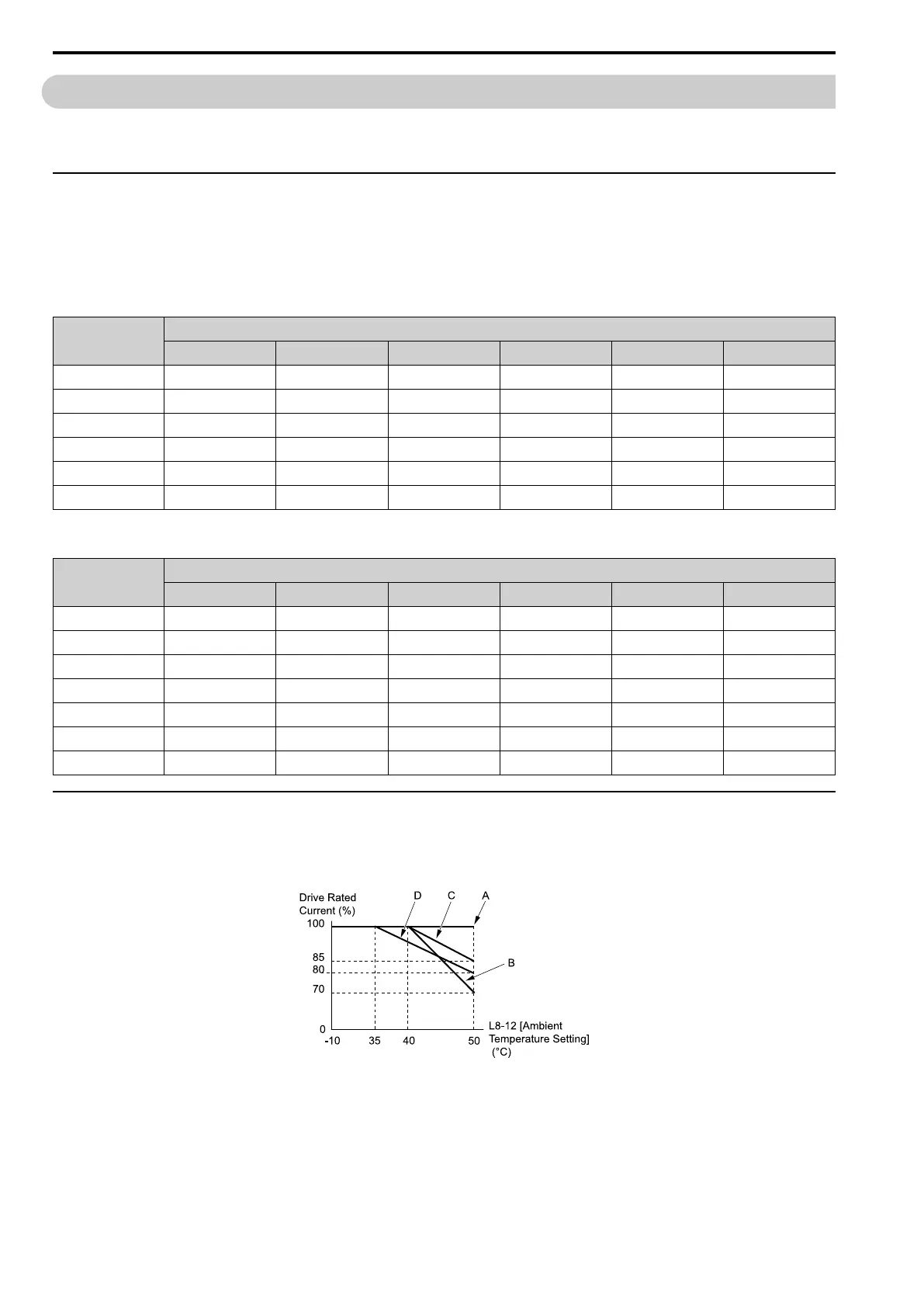
◆ Derating Depending on Ambient Temperature
When you install drives in a place where ambient temperatures are higher than the rated conditions or install
drives side-by-side in the enclosure panel, set L8-12 [Ambient Temperature Setting] and L8-35 [Installation
Method Selection]. Derate the output current as specified in Figure 10.1.
A - L8-35 = 0 [IP20/UL Open Type]
B - L8-35 = 1 [Side-by-Side Mounting]
C - L8-35 = 2 [IP20/UL Type 1]
D - L8-35 = 3 [Finless Installation]
Figure 10.1 Derating Depending on Drive Installation Method
Refer to L8-12: Ambient Temperature Setting on page 341 and L8-35: Installation Method Selection on page 342
for details.

 Loading...


