Installation
4 - 23
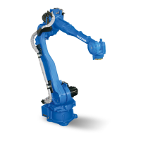
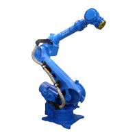
Fig. 4-4: Celling mounted
Fig. 4-5: Wall mounting
Motor base plate After the mounting to the ceiling
Grease outlet opening View
Grease inlet opening Before the mounting to the ceiling
Motor base plate View A
Grease outlet opening Before the mounting to the wall
Grease inlet opening Power input module
After the mounting to the wall
A
1
2
3
3
2
4
6
5
1
4
2
5
3
6
1
2
3
4
5
6
3
2
7
A
1
5
2
6
3
7
4
 Loading...
