5-1
170904-1CD
HW1482870
5 Basic Specifications
5.1 Basic Specifications
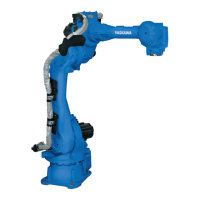
MPL80
II
5 Basic Specifications
5.1 Basic Specifications
Table 5-1: Basic Specifications
1)
Item Model MOTOMAN-MPL80 II
Structure Vertically Articulated
Degree of Freedom 5
Payload 80 kg
Repeatability
2)
±0.07 mm
Range of Motion S-Axis (turning) -180+180
L-Axis (lower arm) -90+135
U-Axis (upper arm) -160+35
B-Axis (wrist pitch/yaw) -15+15
3)
T-Axis (wrist twist) -360+360
Maximum Speed S-Axis 2.97 rad/s, 170/s
L-Axis 2.97 rad/s, 170/s
U-Axis 2.97 rad/s, 170/s
B-Axis 2.97 rad/s, 170/s
T-Axis 6.11 rad/s, 350/s
Allowable Moment
4)
B-Axis 78.4 N•m (8 kgf•m)
T-Axis 20.5 N•m (2.1 kgf•m)
Allowable Inertia
(GD
2
/4)
B-Axis 16 kg•m
2
T-Axis 6.1 kg•m
2
Approx. Mass 550 kg
Protective Structure Basic axis: IP54 or equivalent
Wrist axis only: IP67 or equivalent
Ambient Conditions Temperature 0 to 45C
Humidity 20 to 80% RH at constant temperature
Vibration Acceleration Less than 4.9 m/s
2
(0.5 G)
Others Free from corrosive gas or liquid, or explosive gas.
Free from water, oil, or dust.
Free from excessive electrical noise (plasma).
Power Capacity 4.0 kVA
Noise
5)
70 dB
1 SI units are used in this table. However, gravitational unit is used in ( ).
2 Conformed to ISO9283
3 The range of motion of the B-axis indicates the angle to the ground. With certain postures,
however, motion may be limited by the relative angle between the B-axis and the upper arm.
Refer to section 5.5 “B-Axis Operating Range”.
4 Refer to section 6.1 “Allowable Wrist Load” for details on the permissible moment of inertia.
5 Conformed to ISO6926
1, Measurement is carried out when the maximum load is mounted to the manipulator and
operated in the maximum speed.
2, Measurement is carried out:
- between 1.2m and 1.5m above the ground.
- 400mm away from the P-point maximum envelope.
 Loading...