MYS450L
E1101000117GB01 29
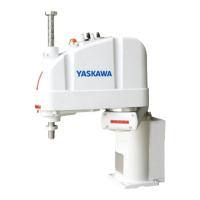
Figure 12: Motion Range Setting by Mechanical Stops
5.5.1 Setting the Mechanical Stops of θ1 and θ2
Both θ1 and θ2 have threaded holes in the positions corresponding to the angle for the
mechanical stop settings. Install the bolts in the holes corresponding to the angle that you
want to set.
1 Mechanical stop of Z (Lower limit mechanical stop)
2 Do not move the upper limit mechanical stop
3
Mechanical stop of θ2 (adjustable)
4
Mechanical stop of θ1 (fixed)
5
Mechanical stop of θ1 (adjustable)
6
Mechanical stop of θ2 (fixed)
Installati
on,
assembl
y
Arm
length
abctefghijkl
Vertical
Articulate
d
45/55/65 +152° +135° +105° +60° +20° +5° -5° -20° -60° -105° -135° -152°
a
b
c
d
e
f
g
h
i
j
k
l
 Loading...


