This document provides assembly instructions for a vanity table, identified by model numbers FTBFVT-0017, FTBFVT-0018, FTBFVT-0019, and FTBFVT-0020, under the product code SDJMY-V3. The manual emphasizes the need for at least two people for installation and recommends professional assembly. It also suggests assembling the unit on a flat, clean, and soft surface to prevent damage.
Function Description:
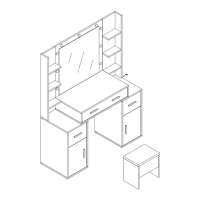
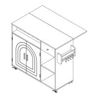
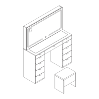
The device is a multi-functional vanity table designed for personal grooming and storage. It features a large mirror, multiple drawers for organizing cosmetics and accessories, and a dedicated space for a magnifying mirror. The overall design aims to provide a comprehensive and organized solution for daily beauty routines.
Important Technical Specifications (Derived from parts list and assembly steps):
Hardware Components:
- Cam Locks and Quickfits: Essential for joining panels securely. The quickfit head should be centered in the cam lock, and the cam lock should be turned clockwise to tighten.
- Drawer Runners: Consist of inner and outer guide rails. These need to be pulled apart before fixing to panels. The drawer runner lock must be pressed to slide the runners apart.
- Outer Guide Rail Installation: Align the guide rail notch towards the inner direction of the drawer. Screws should be fixed according to marked positions. Adjustments can be made side-to-side if the installed position changes.
- Inner Guide Rail Installation: Align the guide rail notch towards the inner direction of the drawer. Screws should be fixed according to marked positions. Adjustments can be made up and down if the installed position changes.
- Screws: Various types and sizes are used throughout the assembly, including:
- Type A: X106 (used in steps 1, 2, 18)
- Type B: X106 (used in steps 3, 4, 5, 6, 7, 8, 13, 18, 19)
- Type C: X28 (8x40MM) (used in steps 1, 2)
- Type D: X126 (3.5x14MM) (used in steps 6, 9, 10, 11, 12, 13, 19)
- Type E: X44 (3.5x35MM) (used in steps 10, 11, 13)
- Type F: X11 (used in steps 10, 11, 13)
- Type G: X11 (7x40MM) (used in steps 3, 7, 8)
- Type H: X2 (used in step 19)
- Type I1: X1 (used in step 15)
- Type I2: X1 (used in step 15)
- Type O: X12 (3x12MM) (used in step 15)
- Connectors:
- Type K: X1 (used in step 6)
- Type L: X2 (used in step 15)
- Type L1: X4 (used in step 15)
- Type L2: X4 (6x35MM) (used in step 15)
- Type L3: X4 (3.5x14MM) (used in step 15)
- Type L4: X4 (3.5x35MM) (used in step 15)
- Mounting Brackets:
- Type M1: X11 (250MM) (used in steps 9, 14)
- Type M2: X11 (250MM) (used in steps 10, 11, 14)
- Wall Fixing Device: Type N: X12 (used in step 15)
Panel Components (Quantities and Usage):
- Item 1: X1 (used in steps 1, 8, 9)
- Item 2: X1 (used in steps 1, 4, 5, 6, 8)
- Item 3: X1 (used in steps 2, 5, 6, 8, 15, 16)
- Item 4: X1 (used in steps 2, 5, 6, 8, 9, 15, 16)
- Item 5: X1 (used in steps 2, 5, 6, 8, 9)
- Item 6: X1 (used in steps 2, 4, 5, 6, 8)
- Item 7: X2 (used in steps 1, 5, 6, 8)
- Item 8: X1 (used in steps 1, 3, 4, 5, 6)
- Item 9: X2 (used in steps 1, 2, 5, 6, 8)
- Item 10: X2 (used in steps 1, 2, 3)
- Item 11: X1 (used in steps 1, 8, 9, 14, 15, 16)
- Item 12: X1 (used in steps 1, 8, 14, 15)
- Item 13: X1 (used in steps 1, 8, 14)
- Item 14: X1 (used in steps 1, 3, 7, 8, 15)
- Item 15: X1 (used in steps 1, 2, 10, 11)
- Item 16: X1 (used in steps 1, 2, 10, 11)
- Item 17: X1 (used in steps 1, 9, 10, 11)
- Item 18: X2 (used in steps 1, 10, 11)
- Item 19: X1 (used in steps 2, 10, 11)
- Item 20: X3 (used in steps 2, 10, 11)
- Item 21: X3 (used in steps 2, 10, 11)
- Item 22: X8 (used in steps 2, 11, 13)
- Item 23: X8 (used in steps 2, 13)
- Item 24: X8 (used in steps 2, 13)
- Item 25: X8 (used in steps 2, 13)
- Item 26: X1 (used in steps 2, 10)
- Item 27: X2 (used in steps 2, 10, 11)
- Item 28: X8 (used in steps 2, 13)
- Item 29: X1 (used in steps 2, 4, 15)
- Item 30: X1 (used in steps 2, 18, 19)
- Item 31: X2 (used in steps 2, 18, 19)
- Item 32: X1 (used in steps 2, 18)
- Item 33: X1 (used in steps 2, 19)
- Item 34: X1 (used in steps 2, 14)
- Item 35: X1 (used in steps 2, 4, 15)
- Item 36: X1 (used in steps 2, 18, 19)
- Item J: X1 (used in step 6)
Usage Features:
- Drawer System: The vanity includes multiple drawers, with specific instructions for installing drawer runners. The runners must be separated before installation, and the lock mechanism needs to be engaged for proper function.
- Magnifying Mirror: A "Part I (Magnifying Mirror with Suction Cup)" is included, which can be freely placed on the dresser table mirror to suit personal needs. This indicates flexibility in mirror placement.
- Cable Management: Step 15 details connecting a line interface and pasting a tape behind a controller into a square groove on the back, suggesting integrated cable management for electronic components (likely lighting for the mirror).
- Wall Fixing Device: A wall fixing device is provided to prevent the cabinet from tipping over, enhancing safety. This device should be installed on the back of the cabinet after assembly. The installation location can be chosen based on individual needs.
Maintenance Features:
- Assembly on Soft Surface: Recommended to prevent scratches or damage during assembly.
- Proper Tightening: Instructions emphasize tightening quickfits until the shoulder is flush with the panel, but not overtightening or undertightening, which is crucial for structural integrity and longevity.
- Screw Alignment: Specific instructions are given for aligning screws with the center of mounting holes for guide rails, ensuring smooth operation of drawers and preventing wear.
- Adjustability: The drawer runner installation instructions mention adjusting the guide rails side-to-side or up and down if the installed position changes, allowing for fine-tuning and maintenance of drawer function over time.
- Safety Precaution: The wall fixing device is a key safety feature, preventing accidents by securing the cabinet to the wall. Regular checks of this device would be part of maintenance.