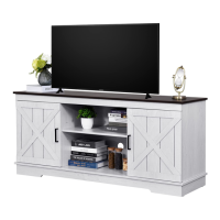
This document provides assembly instructions for a TV stand, identified by model numbers FTLFTS-0002, FTLFTS-0006, and FTLFTS-6002, under the DGHN-V2 series. The primary function of this device is to serve as a TV stand, offering storage and display space for entertainment systems and related items.
Technical Specifications and Components:
The assembly process involves a variety of components, each with specific quantities and purposes. The parts list, detailed on page 2, includes:
-
Wooden Panels:
- Item 1: 1 piece
- Item 2: 1 piece
- Item 3: 2 pieces
- Item 4: 1 piece
- Item 5: 1 piece
- Item 6: 1 piece
- Item 7: 1 piece
- Item 8: 2 pieces
- Item 9: 2 pieces
- Item 10: 2 pieces
- Item 11: 1 piece
- Item 12: 1 piece
- Item 13: 1 piece
- Item 14: 1 piece
- Item 15: 2 pieces (These appear to be smaller support panels or back panels)
-
Fasteners and Hardware:
- (A) Screws (M3.5x14): 36 pieces. These are likely used for general panel attachment.
- (B) Cam Locks: 36 pieces. These are crucial for securing panels together, often used in conjunction with cam dowels.
- (C) Cam Dowels (Ø8x30): 24 pieces. These are inserted into panels and then engaged by cam locks.
- (D) Screws (M7x48): 8 pieces. These longer screws might be for attaching the base or other structural elements.
- (E) Screws (M3.5x14): 48 pieces. Another type of screw, possibly for hinges or smaller attachments.
- (F) Foot Pads: 8 pieces. These are placed at the bottom of the stand to protect the floor and provide stability.
- (G) Door Hinges: 6 pieces. Used for attaching the cabinet doors.
- (H) Screws (M4x20): 8 pieces. These are likely for attaching the back panel or other specific components.
- (I) Handles: 4 pieces. For the cabinet doors.
- (J) Door Pulls: 2 pieces. These are decorative or functional elements for opening the doors.
- (K) Magnetic Catches: 4 pieces. Used to keep the cabinet doors closed.
- (L) Shelf Pins: 4 pieces. For supporting adjustable shelves.
Usage Features:
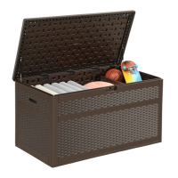
The TV stand is designed with multiple storage compartments, including open shelves and closed cabinets with doors. The "Explosion Diagram" on page 3 illustrates the overall structure, showing a top panel (1), side panels (11, 12, 13, 14), a base (8), and internal shelves (10). The presence of hinges (G) and handles (I, J) indicates that the stand features cabinet doors, likely with a decorative "X" pattern as seen in the main image. The magnetic catches (K) ensure that these doors remain securely closed. Foot pads (F) are included to protect the floor and provide stability.
The stand appears to have a central open shelf area, suitable for media players, gaming consoles, or soundbars, and two side cabinets for concealed storage. The design incorporates a classic, possibly farmhouse-style aesthetic with the "X" pattern on the doors.
Assembly Process and Maintenance Features:
The assembly instructions are broken down into 17 steps, with detailed diagrams for each. Key aspects of the assembly process include:
- Step 1 (Page 3): Attaching cam dowels (C) and cam locks (B) to panels 11, 12, 13, and 14. This step also involves attaching screws (A) to these panels.
- Step 2 (Page 4): Connecting panels 11, 12, 13, and 14 using cam locks (B) and cam dowels (C). This forms the basic side structures of the stand.
- Step 3 (Page 4): Attaching the top panel (1) to the assembled side structures using screws (A).
- Step 4 (Page 5): Connecting the bottom panel (8) and internal shelves (10) to the side structures using cam locks (B) and cam dowels (C).
- Step 5 (Page 5): Attaching the back panel (4) to the main structure using screws (A).
- Step 6 (Page 6): Securing the back panels (3) to the rear of the stand.
- Step 7 (Page 6): Attaching the top and bottom support rails (2) to the main structure using screws (D) and cam dowels (C).
- Step 8 (Page 7): Attaching the base (5, 6) to the bottom of the stand using screws (A).
- Step 9 (Page 7): Securing the foot pads (F) to the bottom of the stand.
- Step 10 (Page 8): Attaching the shelf pins (L) to the internal shelves, allowing for height adjustment.
- Step 11 (Page 8): Installing the magnetic catches (K) and hinges (G) to the cabinet doors and the main structure using screws (E) and (F).
- Step 12 (Page 9): Attaching the handles (I) and door pulls (J) to the cabinet doors.
- Step 13 (Page 9): Installing the back panel (H) to the rear of the stand using screws (H).
- Step 14 (Page 10): Attaching the cabinet doors to the stand using hinges (G) and screws (E).
- Step 15 (Page 10): Adjusting the cabinet doors for proper alignment. This step highlights three adjustment options:
- Up/Down Adjustment: Tightening the screw marked green adjusts the door's vertical position.
- Front/Back Adjustment: Tightening the screw marked green adjusts the door's depth.
- Left/Right Adjustment: Turning the screw marked green adjusts the door's horizontal position.
- These adjustments are crucial for ensuring the doors close properly and are aesthetically aligned.
- Step 16 (Page 11): Finalizing the door installation and ensuring all components are secure.
- Step 17 (Page 11): "Installation Completed" indicates the final assembled product.
Important Notices and Recommendations:
The manual includes critical notices for a smooth assembly experience:
- Follow Instructions: Users are advised to strictly follow the installation instructions and confirm all accessories are present before starting.
- Partial Tightening: Screws should not be fully tightened during initial assembly. Full tightening should only occur once all pieces are correctly assembled, allowing for minor adjustments during the process. This is a common practice in furniture assembly to prevent misalignment and stress on components.
- Troubleshooting: In case of installation problems, two solutions are offered:
- Refer to the installation video tutorial available on the Amazon product page.
- Contact customer service for assistance.
This TV stand is designed for home use, providing a functional and aesthetically pleasing solution for organizing entertainment equipment. The detailed instructions and troubleshooting advice aim to make the assembly process manageable for the end-user. Regular maintenance would involve checking the tightness of screws and adjusting door alignments as needed over time.