<2. Handling Cautions>
2-5
IM 01C25B01-01E
Model: EJX Series Date: October 22, 2003
Re v.2: July 16, 2019 Doc. No.: IFM022-A12 P.1
Yokogawa Electric Corporation
Control Drawing
Class I, II, III, Division 1
Groups A, B, C, D, E, F, G
Class I, Zone 0, Group IIC
EJX Series
Class I, Zone 2, Group IIC
Transmitter
(Refer to Note 4)
Associated Apparatus
(Safety Barrier)
General
Purpose
General
Purpose
Model: EJX Series Date: October 22, 2003
Re v.3: July 16, 2019 Doc. No.: IFM022-A12 P.2
Yokogawa Electric Corporation
Specific conditions of use:
- Precautions shall be taken to minimize the risk from electrostatic discharge of
painted parts.
- When the enclosure of the Pressure Transmitters is made of aluminum alloy, if it is
mounted in Zone 0, it must be installed such that, even in the event of rare
incidents, an ignition source due to impact and/or friction sparks is excluded.
Entity Parameters [Groups: A, B, C, D, E, F and G]
Vmax: 30 V
Imax: 200 mA
Pmax: 1 W
Ci: 6 nF
Li: 0 µH
Entity Parameters [Groups: C, D, E, F and G]
Vmax: 30 V
Imax: 225 mA
Pmax: 1 W
Ci: 6 nF
Li: 0 µH
Notes:
1. Installation must be in accordance with the National Electric Code (NFPA70),
ANSI/ISA-RP12.06.01, and relevant local codes.
2. The Associated Apparatus must be FM-approved.
3. The following conditions must be satisfied.
Voc (or Uo) ≤ Vmax
Isc (or Io) ≤ Imax
Po ≤ Pmax
Ca (or Co) ≥ Ci + Ccable
La (or Lo) ≥ Li + Lcable
4. In case Nonincendive Field Wiring Concept is used for the interconnection,
FM-approved Associated Nonincendive Field Wiring Apparatus, which meets the
above conditions, must be used as the General Purpose Equipment.
5. The General Purpose Equipment connected to the Associated Apparatus must not
use or generate a voltage more than Um of the Associated Apparatus.
6. The control drawing of the Associated Apparatus must be followed when installing
the equipment.
7. Dust-tight conduit seals must be used when installed in Class II or Class III
environments.
8. WARNING –ELECTROSTATIC CHARGE MAY CAUSE AN EXPLOSION HAZARD.
AVOID ANY ACTIONS THAT CAUSE THE GENERATION OF ELECTROSTATIC
CHARGE, SUCH AS RUBBING WITH A DRY CLOTH ON COATING FACE OF THE
PRODUCT.
9. WARNING – SUBSTITUTION OF COMPONENTS MAY IMPAIR INTRINSIC
SAFETY AND SUITABILITY FOR HAZARDOUS LOCATION
b. FM Explosionproof Type
Caution for FM explosionproof type.
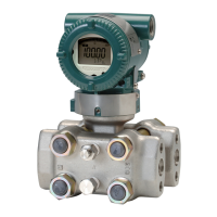
Note 1. EJX/EJA-E Series pressure transmitters
with optional code /FF1 are applicable for
use in hazardous locations.
• Applicable Standard: FM3600:2018,
FM3615:2018, FM3810:2018,
NEMA 250:2003, ANSI/UL 61010-1:2012,
ANSI/UL 61010-2-30:2012
• Explosionproof for Class I, Division 1,
Groups B, C and D.
• Dust-ignitionproof for Class II/III, Division 1,
Groups E, F and G.
• Enclosure: Type 4X
• Temperature Class: T6
• Ambient Temperature: –40 to 60°C
• Supply Voltage: 42 V dc max.
32 V dc max. (FOUNDATION Fieldbus and
PROFIBUS PA type)
9 to 28 V dc, 27 mW (Low Power type)
• Output signal: 4 to 20 mA
15 mA (FOUNDATION Fieldbus and
PROFIBUS PA type)
1 to 5 V (Low Power type)
Note 2. Wiring
• All wiring shall comply with National Electrical
Code ANSI/NFPA70 and Local Electrical
Codes.
• When installed in Division 1, “FACTORY
SEALED, CONDUIT SEAL NOT
REQUIRED.”
• Wiring connection for output signal code Q
(Low Power type) shall follow the diagram
below.
F0211.ai
Three-Wire Connection
Pressure Transmitters
Power Supply
Voltmeter
SUPPLY
+
SUPPLY
–
A
+
–
+
–
Four-Wire Connection
Pressure Transmitters
Power Supply
Voltmeter
SUPPLY
+
SUPPLY
–
A
+
–
+
–

 Loading...


