General Instruction Manual
Wiring
Grounding connections and sensor circuits
44 / 90
IM 01U10B00-00EN-R, 3rd edition, 2018-07-09
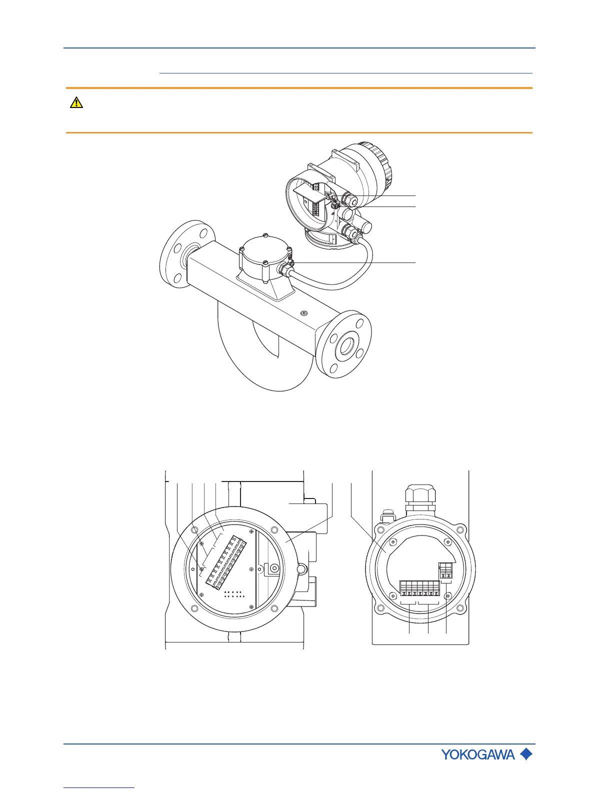
7.2 Grounding connections and sensor circuits
WARNING
Risk of injury from electrical shock due to inadequate grounding
▶ Perform potential equalization at the grounding terminals provided for this purpose
according to the figure “Grounding connections on transmitter and sensor”.
Fig.27: Grounding connections on transmitter and sensor
1 Grounding screw in transmitter terminal box for grounding conductor
2 Grounding terminal on transmitter for potential equalization
3 Grounding terminal on sensor for potential equalization
D +
D -
S1 +
S1 -
S2 +
S2 -
TP1
TP2
TP3
D +
D -
S1 +
S1 -
S2 +
S2 -
TP1
TP2
TP3
COM
3 2 1
1 2 3 4 5 6
Fig.28: Connection terminal circuits (transmitter on the left side, sensor on the right side)
1 Driver circuit (D+/D-) 4 Signal grounding
2 Sensor circuits (S1+/S1-, S2+/S2-) 5 Transmitter
3 Temperature measurement circuit
(TP1, TP2, TP3)
6 Sensor
 Loading...


