4-5
IM DL850E-01EN
Trigger Slope (Slope)
Slope refers to the movement of the signal from a low level to a high level (rising edge) or from a high level to a
low level (falling edge). When a slope is used as one of the trigger conditions, it is called a trigger slope.
The following trigger slope settings are available for triggering the DL850E/DL850EV.
The DL850E/DL850EV triggers when the trigger source changes from a
level below the trigger level to a level above the trigger level (rising).
The DL850E/DL850EV triggers when the trigger source changes from a
level above the trigger level to a level below the trigger level (falling).
The DL850E/DL850EV triggers on both rising and falling edges.
* can be selected only when a simple trigger is used with an analog trigger source.
Trigger Hysteresis (Hysteresis)
Noise rejection establishes a trigger level margin (hysteresis) so that the DL850E/DL850EV does not trigger if
the signal level change is within the margin.
For each type of measured signal, you can set the hysteresis around the trigger level to one of the options listed
below. You cannot set hysteresis when the trigger source is set to Time, External, Line, or a logic signal.
Voltage Approx. ±0.1 div Approx. ±0.5 div Approx. ±1 div
Temperature Approx. ±0.5°C (K) Approx. ±1°C (K) Approx. ±2°C (K)
Strain Approx. ±2.5% of the range
Approx. ±12.5% of the
range
Approx. ±25% of the range
Acceleration
Approx. ±0.1 div of the
range
Approx. ±0.5 div of the
range
Approx. ±1 div of the range
Frequency,
CAN,
LIN
Approx. ±0.01 div of the
range
Approx. ±0.5 div of the
range
Approx. ±1 div of the range
* The above values are approximate values. They are not strictly warranted.
Trigger Hold-Off (Hold Off)
The trigger hold-off feature temporarily stops the detection of the next trigger once a trigger has occurred. This
feature is useful in cases when you want to change the waveform acquisition interval, such as when you are
observing a PCM (pulse code modulation) code or other pulse train signal or when you are using the history
feature.
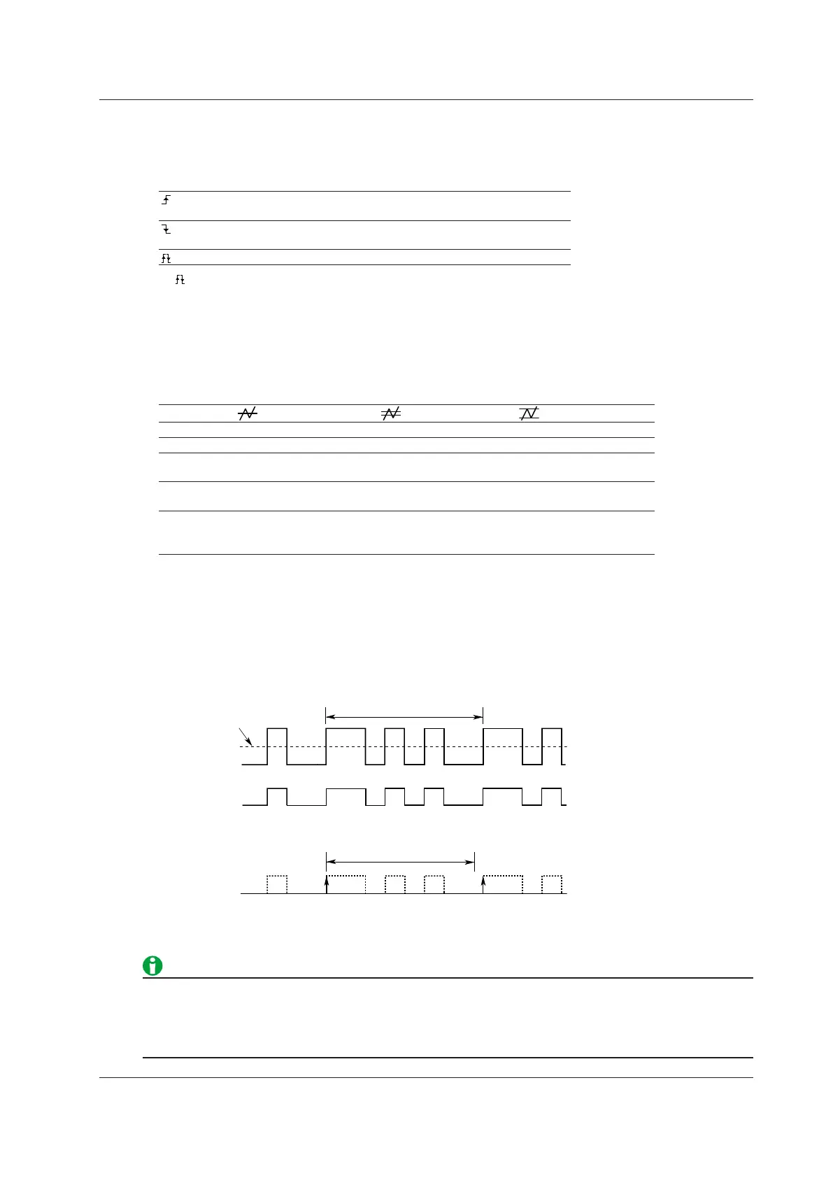
Input signal
Repeating interval: T
Trigger level
Trigger source
signal
t
Trigger signals that have been suppressed over the hold-off
period t (when the trigger slope is set to rising)
Selectable range: 0.00 μs to 10000000.00 μs (10 s). The default settings is 0.00 μs
Resolution: 0.01 μs
• To trigger with the hold-off time set to 50 ms or longer, set the trigger mode to Normal.
• For the A -> B(N) and A Delay B triggers, the hold-off time applies only to state condition B.
• The trigger hold-off time does not apply to the simple trigger when the trigger source is Time, to the period
trigger, or to the manual trigger.
4 Triggering
 Loading...
