2-2
<Toc> <Ind>
TI 05C01E02-01E 1st Edition : Oct. 31, 2001-00
■ Standard type
● UT130 Standard Type: Model and Suffix Codes
Model
Model and Suffix Codes
Suffix codes Description
UT130 Temperature controller (48 x 48 x 100mm)
Control
output
Relay output (time-proportional PID or on/off control)
Voltage pulse output (time-proportional PID control)
Fixed
N Fixed
Options
/AL
/HBA
/RS
/V24
Alarm outputs (2 points) (Note1)
Heater disconnection alarm (includes the function of " /AL" option) (Note 1)
Communication function (Note 2)
Power Supply 24V DC / 24V AC
Note 1: The "/AL" and "/HBA" options cannot be specified at the same time. The "/HBA" option includes the function
of "/AL" option.
Note 2: When specifying the "/RS" option, be sure to order the required number of copies of the Communication
Functions User’s Manual (IM05C01E12-10E) separately. (See Page 2-8.)
-R
-V
Check the package contents against the list below.
• Temperature controller (of ordered model)
......
1
• Mounting bracket
...............................
1
• User’s Manual (IM 05C01E02-01E)
.............
1
● UT150 Standard Type: Model and Suffix Codes
Model
Model and Suffix Codes
Suffix Codes Description
UT150 Temperature controller (48 x 48 x 100 mm)
Control
output
-R
-V
-A
Relay output (time-proportional PID or on/off control)
Voltage pulse output (time-proportional PID control)
4 to 20mA output ( current PID) (Note1)
Fixed
N Fixed
Option
/AL
/HBA
/EX
/RET
/RS
/V24
Alarm outputs (2 points) (Note2)
Heater disconnection alarm (includes the function of " /AL" option)
(Notes 2 and 3)
SP1/SP2 switching, starting of timer, and RUN/STOP switching byexternal contacts
(Notes 4 and 5)
PV retransmission output in 4 to 20mA (Note 3)
Communication function (Notes 4 and 6)
Power Supply 24V DC / 24VAC
Note 1: The " /HBA" option cannot be specified when selecting "4 to 20mA output" as a control output type.
Note 2: The "/AL" and "/HBA" options cannot be specified at the same time. The "/HBA" option includes the function
of "/AL" option.
Note 3: The "/HBA" and "/RET" options cannot be specified at the same time.
Note 4: "/EX" and "/RS" options cannot be specified at the same time.
Note 5: Two points of external contact inputs are available. Select 2 functions among SP1/SP2 switching, starting of
timer, and RUN.STOP switching.
Note 6: When specifying the "/RS" option, be sure to order the required number of copies of the Communication
Functions User s Manual (IM05C01E12-10E) separately. (See Page 2-8)
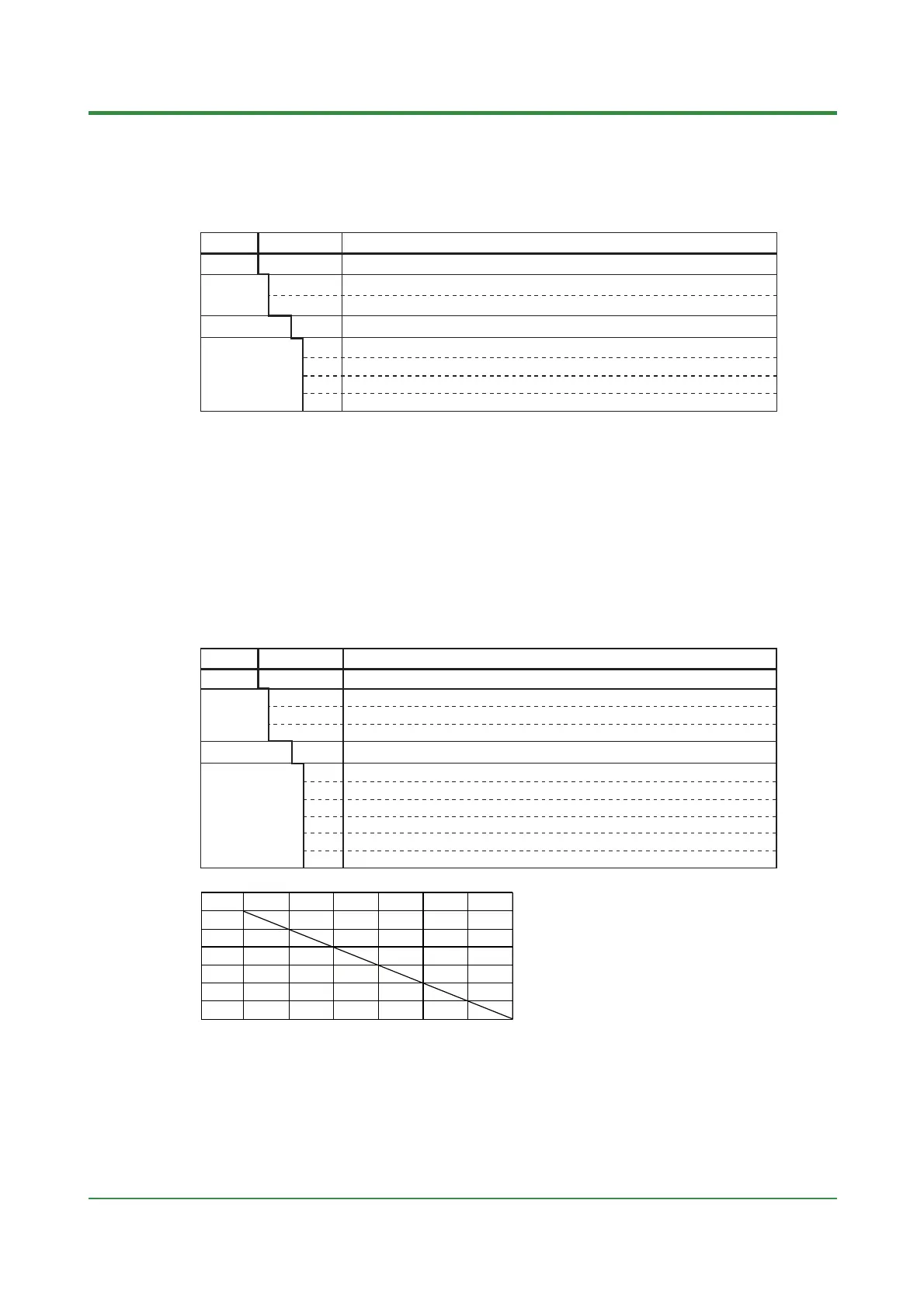
UT150 Table of Option Combination
/AL
/HBA
/EX /RET
/RS
/V24
AA
A
A
AA
A
A
AA
A
AA
A
AA
A
A
A
A
AN/A
N/AN/A
N/A
N/A
N/A
N/A
A
A
/AL
/HBA
/EX
/RET
/RS
/V24
Check the package contents against the list below.
• Temperature controller (of ordered model)
......
1
• Mounting bracket
...............................
1
• User’s Manual (IM 05C01E12-01E)
.............
1
A : Available
N/A : Not available
 Loading...
