<Toc> <Ind>
1-1
TI 05C01E02-01E 1st Edition : Oct. 31, 2001-00
1.
DESCRIPTION OF TEMPERATURE CONTROL
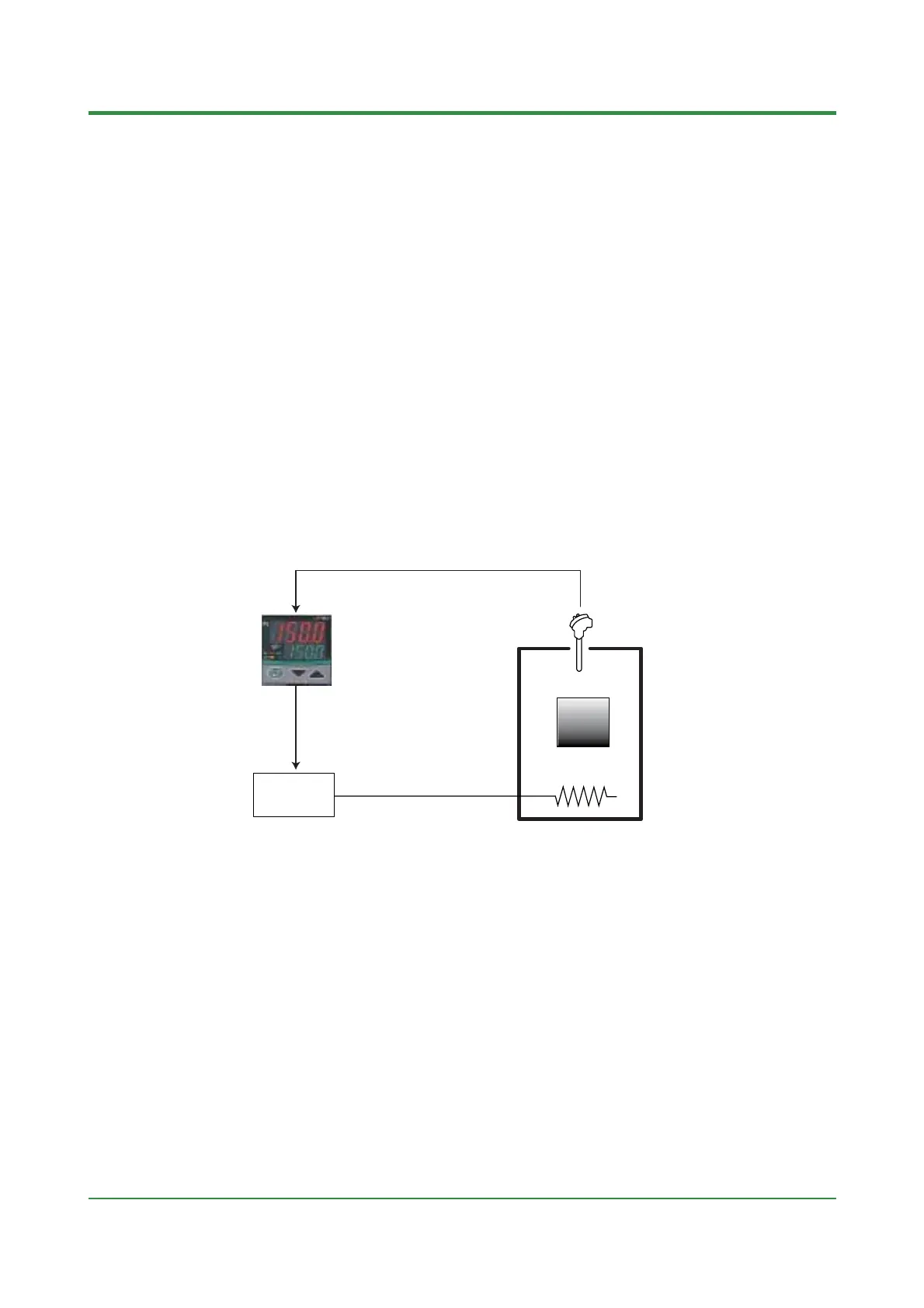
■ Temperature Controller
The temperature controller is used to keep the fixed temperature of such as a furnace
(controlled object). In general, the temperature controller has temperature indicating
display and setpoint setting display, generates a control signal according to the differ-
ence between a indicating value (measured temperature value) and SP to finally make
the temperature agree with SP.
Sensors such as thermocouple (TC) or RTD can be connected for measuring a tem-
perature. And output types such as relay output or current output (4 to 20mA) are
prepared according to the operating terminal (heater, valve, and the like) that actually
controls a temperature.
Heater
Work
Controlled object
Measuring
object
•Thermocouple
• RTD
• SSR
• Power regulator
• Relay
• Voltage pulse
• Current
Control output
Measured input
Operating
device
 Loading...
