EasyManua.ls Logo

York International ZQ Series User Manual

York International ZQ Series
92 pages
To Next Page IconTo Next Page
Page #1 background imageLoading...
Page #1 background image
5943355-UIM-A-1020 York International Corporation, 5005
York Drive, Norman, OK 73069
2020-10-01
Johnson Controls Ducted Systems
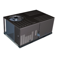
INSTALLATION MANUAL ZQ SERIES
3-5ton 60 Hertz R-410A

Table of Contents

Questions and Answers:

York International ZQ Series Specifications

General IconGeneral
BrandYork International
ModelZQ Series
CategoryAir Conditioner
LanguageEnglish

Summary

General

Safety considerations

Explains safety alert symbols and signal words (Danger, Warning, Caution).

Installation

Installation Safety Information

Read installation instructions before proceeding; outdoor unit combination.

Preceding Installation

Instructions for removing shipping brackets and preparing the unit base.

Limitations

Constraints and requirements for unit installation and operation.

Location

Guidelines for selecting a suitable outdoor installation location.

Clearances

Rigging And Handling

Instructions for safely moving and lifting the unit using chains or forklifts.

Ductwork

Condensate Drain

Details on providing a condensate drain connection and trap.

Duct Covers

Instructions for covering and reusing duct panels for side duct applications.

Compressors

Filters

Information on filter types, installation, and cleaning.

Power And Control Wiring

Requirements for field wiring, fuses, and disconnects according to codes.

Thermostat Wiring

Typical Field Power and Control Wiring

Typical Power Wiring

Illustrates typical power wiring for ETC systems.

Typical Smart Equipment™ Control Wiring

Illustrates typical control wiring for Smart Equipment™ systems.

Electrical data

ZQ04 to 06 Standard Static Indoor Blower - Without Powered Convenience Outlet

Electrical data for ZQ04-06 units with standard static indoor blower.

ZQ04 to 06 Standard Static Indoor Blower - With Powered Convenience Outlet

Electrical data for ZQ04-06 units with standard static indoor blower.

ZQ04 to 06 Medium Static Indoor Blower - Without Powered Convenience Outlet

ZQ04 to 06 Medium Static Indoor Blower - With Powered Convenience Outlet

Electrical data for ZQ04-06 units with medium static indoor blower.

ZQ04 to 06 High Static Indoor Blower - Without Powered Convenience Outlet

ZQ04 to 06 High Static Indoor Blower - With Powered Convenience Outlet

Electrical data for ZQ04-06 units with high static indoor blower.

Physical data

Optional Gas Heat

Gas Piping

Guidance on sizing and routing gas piping according to codes.

Gas Connection

Details on gas supply line routing, connections, and recommendations.

Combustion Air and Flue Exhaust

Options/Accessories

Economizer

Describes factory or field installed economizer options.

Power Exhaust

Details field installed power exhaust accessories for different applications.

Rain Hood

Information on packaging and location of rain hood components.

Blower Phasing

Instructions for checking and correcting blower rotation direction.

Blower Rotation

Belt Tension

Altitude and Temperature Correction for CFM, Static Pressure and Power

Guidance for adjusting airflow rates based on altitude and temperature.

Drive Selection

Airflow Performance

ZQ04-06 Side Duct Application (Belt Drive)

ZQ06 (5.0 Ton) Side Duct

Airflow performance data for ZQ06 side duct belt drive application.

ZQ04-06 Side Duct Application (Direct Drive)

ZQ04-06 Bottom Duct Application (Belt Drive)

RPM Selection

Indoor Blower Specifications

Details blower motor and sheave specifications for drive adjustments.

Supply Air Drive Adjustment

Everyday Thermostat Control (ETC)

Everyday Thermostat Control operation

Explains how compressors are controlled by thermostat inputs (Y1, Y2).

Gas Heat Unit Configuration

Electric Heat Unit Configuration

Describes unit operation for electric heat stages and fan control.

VFD Operation

Details the VFD output signal for fan speed control.

Smart Equipment™™ unit control board

Operation

Compressor Operation

Details on how compressors are controlled via thermostat inputs and safety devices.

Cooling sequence of operation

Describes the unit's operation during cooling mode based on thermostat calls.

Continuous Blower

How to enable continuous indoor blower operation via thermostat.

Intermittent Blower

How the blower operates intermittently with thermostat cooling/heating calls.

No Outdoor Air Options

Operation of cooling system without outdoor air options, including fan on delay.

Economizer With Single Enthalpy Sensor for ETC, and Economizer With Dry Bulb Sensor for Smart Equipment™

Operation of economizer with single enthalpy or dry bulb sensors for cooling.

Economizer With Dual Enthalpy Sensors

Operation of economizer with dual enthalpy sensors for improved efficiency.

Economizer With Power Exhaust

Operation of economizer combined with power exhaust for ventilation control.

Motorized Outdoor Air Dampers

How motorized outdoor air dampers operate based on thermostat call.

Cooling Operation Errors

High-Pressure Limit Switch

How the unit responds to high-pressure limit switch trips during cooling.

Low-Pressure Limit Switch

How the unit responds to low-pressure limit switch openings during cooling.

Freezestat (ETC Only)

Operation and lockout conditions related to the freezestat.

Evaporator Low Limit (Smart Equipment™™™ Control Only)

How the unit responds to low evaporator temperatures detected by EC1.

Low Ambient Cooling (Smart Equipment™™ Control Only)

Operation in low ambient mode, including compressor cycling for defrost.

Safety Controls

Monitors safety inputs like freezestat, high/low pressure switches.

Compressor Protection

Discusses inherent compressor protection and anti-short cycle delay.

Electric Heating Sequence of Operations

Electric Heat Operating Errors

Details errors related to temperature limits in electric heat operation.

Safety Controls

Monitors temperature limit switch for electric heat units.

Temperature Limit Switch (TLS)

Describes the function and reset of the temperature limit switch.

Flash Codes or Error Messages

How error messages are displayed for electric heat system faults.

Reset

How to reset electric heat flash codes by adjusting thermostat.

Electric Heat Anticipator Setpoints

Importance of correct anticipator setpoints for heat cycle length.

Gas Heating Sequence of Operations

Two Stage Furnace Only

Operation of two-stage gas furnaces for heating, including staging logic.

Gas Heat Operation Errors

Details errors related to temperature limits in gas heating operation.

Gas Valve

Centrifugal Switch

Function of the centrifugal switch for draft motor operation and safety.

Roll-out Switch

How the rollout switch detects and responds to flame rollout.

Flame Sense Circuit

Monitoring the flame sensor for pilot flame stability and ignition.

Flash Codes or Error Messages

How error messages are displayed for gas heat system faults.

Smart Equipment™™ Economizer Board Details

Indoor Air Quality AQ

Gas Heating Operation

Describes heating stage control via W1/W2, ignition process, and fan delays.

Gas Heat Ignition Control Board Function

Ignition Control Board on Standby

Describes the ICB state when idle, monitoring for calls and flame.

Call for heat

How the ICB responds to a call for heat, checking pressure switch.

Pressure switch proving

Process of verifying the low pressure switch operation for safety.

Pre-purge

The 15-second period before ignition to purge the heat exchanger.

Ignition trial period

The 10-second period where the ICB attempts to ignite the gas.

Flame stabilization period

Period after ignition to ensure stable flame before main burner operation.

Main Burner operation

How the main burner operates in high heat warm-up and low heat modes.

Lockout

Conditions and methods for resetting ignition control lockouts.

High temperature limit switch

How the system responds to high temperature limit switch activation.

Roll-out switch

How the rollout switch detects and responds to flame rollout.

Power interruptions

How power interruptions affect the ignition control sequence.

Flame present with Gas off

Response to detecting flame when the gas valve should be closed.

Welded gas valve relay response

How the system reacts to a gas valve relay that is stuck open or closed.

Start-Up (Cooling)

Prestart Check List

Checks to perform before starting the unit for cooling operation.

Cooling operating instructions

Steps for operating the unit during the cooling season.

Post Start Check List

Checks to perform after the unit has started in cooling mode.

Start-up (Gas heat)

Pre-Start Check List

Pre-start checks for gas heat operation, including gas type and air inlets.

Gas heat operating instructions

Instructions for lighting main burners and initiating gas heat operation.

Post Start Checklist

Checks after energizing control circuit and during heating operation.

Shut Down

Procedures for safely shutting down the unit's heating section.

Checking Gas Heat Input

Single Stage Gas Heat

Procedure to determine gas flow rate and input for single-stage gas heat.

Two Stage Gas Heat

Procedure to determine gas flow rate and input for two-stage gas heat.

Manifold Gas Pressure Adjustment

Single Stage

Procedure for adjusting manifold gas pressure for single-stage gas heat.

Two Stage

Procedure for adjusting manifold gas pressure for two-stage gas heat.

Adjustment Of Temperature Rise

Burners/Orifices Inspection/Servicing

Start up for Units Equipped for FER

Direct Drive

Startup procedure for direct drive FER units with specific wiring leads.

Troubleshooting

Table 61: Everyday Thermostat Controls fault codes

List of fault codes for everyday thermostat control systems.

Table 62: Flash Codes for the Gas Heat Ignition Control Board

Flash codes for the gas heat ignition control board and corrective actions.

Charging Tables

Control Board Navigation Components

Start-Up Sheet

EQUIPMENT STARTUP

Steps and required tools for equipment startup using LCD or MAP Gateway.

SAFETY WARNINGS

DESIGN APPLICATION INFORMATION

Information required from specifying engineer for system design and CFM.

REFERENCE

General Inspection

Checklist for general unit inspection before operation.

Air Moving Inspection

Inspection steps for drive components, belt tension, and pulleys.

Exhaust Inspection

Checks for exhaust components like hub, fan blade, rotation, and mounting.

Economizer Inspection

Inspection steps for economizer components and settings.

OPERATIONAL MEASUREMENTS - Air Flow

ELECTRICAL DATA

Section for recording nameplate and measured electrical data for unit components.

OPERATING MEASUREMENTS - COOLING

OPERATING MEASUREMENTS - GAS HEATING

Measurements for gas heating system components like manifold pressure and temperature rise.

OPERATIONAL MEASUREMENTS - STAGING CONTROLS

FINAL - INSPECTION

Final checks on control setpoints, options, and securing panels.

Related product manuals