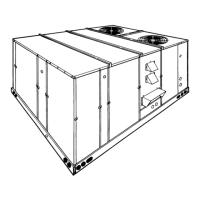
DUCT COVERS - Units are shipped with the bottom
duct openings covered. An accessory flange kit is avail-
able for connecting side ducts.
For
bottom duct applications:
1. Remove the side panels from the supply and return
air compartments to gain access to the bottom
supply and return air duct covers.
2. Remove and discard the bottom duct covers. (Duct
openings are closed with sheet metal covers except
when the unit includes a power exhaust option. The
covering consists of a heavy black paper composition.)
3. Replace the side supply and return air compartment
panels.
For
side duct applications;
1. Replace the side panels on the supply and return air
compartments with the accessory flange kit panels.
2. Connect ductwork to the duct flanges on the rear of
the unit.
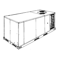
FIG. 10
- DIMENSIONS & CLEARANCES - 15 & 20 TON
RETURN AIR
OUTDOOR AIR
(Economizer)
SUPPLY AIR
CONDENSER AIR
RETURN
AIR
OUTDOOR
AIR
SUPPLY
AIR
GAUGE LINE
ACCESS
COM PRESSOR
ACCESS
S U P P L Y A IR
ACCESS
CO NDENSER SECTION
RETURN AIR
ACCESS
OUTDOOR AIR
CO M PARTMENT
ACCESS
1 " N P T F E M A L E
COND. DRAIN
CONNECTION
FILTER
ACCESS
DOT PLUG
(F o r p re ss u re
drop reading)
EVAPORATOR
SECTION
40-1/2"
28-5/8" (15 Tons)
39-5/8" (20 Tons)
27-3/4"
5-1/8"
18-5/8"
5-1/2"
40-3/8"
REAR
VIEW
DETAIL “X”
(ACCESSORY SIDE SUPPLY AND RETURN AIR OPENINGS)
Front 36"
Back
24" (Less Economizer)
49" (With Economizer)
Left Side (Filter Access)
24" (Less Economizer)
36"
3
(With Economizer)
Right Side (Cond. Coil) 36"
Below Unit
1
20"
Above Unit
2
72" With 36" Maximum
Horizontal Overhang
(For Condenser Air
Discharge Outlet)
1Units (applicable in U.S.A. only) may be installed on combustible floors
made from wood or class A, B or C roof covering material.
2
Units must be installed oudoors. Overhanging structures or shrubs should
not obstruct condenser air discharge outlet.
3
If economizer is factory installed, the assembled hood kit must be removed
prior to final installation. This hood is 54" long.
NOTE:
A one-inch clearance must be provided between any combustible material
and the supply air ductwork for a distance of 3 feet from the unit.
The products of combustion must not be allowed to accumulate within a
confined space and recirculate.
Locate unit so that the vent air outlet hoods are at least:
•
Three (3) feet above any forced air inlet located within 10 horizontal feet
(excluding those integral to the unit).
•
Four (4) feet below, 4 horizontal feet from, or 1 foot above any door or gravity
air inlet into the building.
•
Four (4) feet from electric meters, gas meters, regulators and relief equip-
RETURN
AIR
SUPPLY
AIR
BOTTOM SUPPLY
AND RETURN
AIR OPENING S
(S ee N ote)
(B )
POW ER W IRING
ENTRY
(A )
CONTROL W IRING
ENTRY
NOTE:
For curb m ounted units, refer to the curb hanger
dim ensions of the curb for the proper size of the
s u p p ly a n d re tu rn a ir d u c t c o n n e c tio n s .
UNIT BASE W ITH RAILS
Show n separately to illustrate
Bottom D uct openings, Pow er
and G as P iping C onnection
lo c a tio n s
12-1/2"
9-1/4"
8-1/8"
9-3/4"
3-3/4"
(B )
POW ER W IRING
ENTRY
(A )
CONTROL W IRING
ENTRY
92"
CONDENSER
COILS
OPTIONAL
COIL GUARD
COM PRESSOR
ACCESS
(S ee detail "X ")
E C O N O M IZ E R / M O T O R IZ E D D A M P E R ,
FIXED OUTDOOR INTAKE AIR AND
POW ER EXHAUST RAIN HO ODS
(S ee detail "Y ")
FIELD-SUPPLIED
DISCONNECT SW ITCH
LO C ATIO N
BLOW ER
ACCESS
BLOW ER MOTOR
ACCESS
BLOW ER
CO M PARTMENT
ACCESS
(A u x ilia ry )
DOT PLUG
(F o r p re ss u re
Drop Reading)
FRO NT
VIEW
CONTROL BOX
ACCESS
21"
5"
9-3/4"
11-1/2"
2-3/4" 21-1/2"
33"
35"
5-7/8"
46-5/8"
7-1/8"
6-3/8"
VENT AIR
OUTLET
HOODS
COM BUSTION
AIR INLET
HOOD
GAS HEAT
ACCESS
(C )
GAS SUPPLY
ENTRY
46-5/8"
11-1/8"
(D )
GAS SUPPLY
ENTRY
48-5/8" (15TO N )
52-5/8" (20 TO N)
12-1/4" (15 TO N)
35-1/4" (20 TO N)
125-1/4" (15 TO N )
136-1/4" (20 TO N )
All dimensions are in inches. They are sub-
ject to change without notice. Certified di-
mensions will be provided upon request.
HOLE
OPENING
SIZE
(DIA.)
USED FOR
A
1-1/8" KO
Control
Wiring
Front
3/4" NPS (Fem.) Bottom
B
3-5/8" KO
Power
Wiring
Front
3" NPS (Fem.) Bottom
C 2-3/8" KO Gas Piping (Front)
D 1-11/16" Hole Gas Piping (Bottom)*
*Opening in the bottom of the unit can be located by the slice
in the insulation.
UTILITIES ENTRY DATA
SUPPLY
AIR
COM PARTM ENT
POW ER
EXHAUST
RAIN
HOOD
(o n
Return
Air
C om partm ent)
ECONOMIZER
MOTORIZED
DAMPER
R A IN H O O D
(on O utdoor Air C om partm ent)
ECONOMIZER
/
MOTORIZED
DAM PER
AND
POW ER
EXHAUST
RAIN
HOODS
FIXED
OUTDOOR
AIR
IN T A K E
HOOD
(located on
R e tu rn A ir
C om partm ent)
1" CO N DEN STATE
DRAIN
(M ust be trapped)
REAR VIEW
L H V IE W
D E T A IL "Y "
UNIT W ITH RAIN HOODS
36"
66-1/2"
92"
36-1/4"
5"
34-1/4"
16-1/8"
2"
CLEARANCES
530.18-N6Y
Unitary Products Group 11

 Loading...