EasyManua.ls Logo

York E2FB120 - User Manual

York E2FB120
16 pages
To Next Page IconTo Next Page
Loading...
GENERAL
These heat pump units are designedfor outdoorinstallationon
a roof or at ground level. Every unit is completely piped and
wiredatthefactoryandis shippedreadyforimmediateinstalla-
tion. Only the liquid and vapor lines to the indoor coil, the con
-
trol wiring and the main power wiring are required to complete
the installation. Each unit is dehydrated, evacuated, leak
tested and pressure tested at 450 psig before being pressur
-
ized with a holding charge of Refrigerant-22 for shipment
and/or storage.
Every unit includes a heavy-duty compressor with line break
overload protection, a suction line accumulator, a 4-way re
-
versing valve, a filter-drier, an expansion valve, a distributor, a
check valve, and a copper tube/aluminum fin coil.
All controlsare readilyaccessibleformaintenance,adjustment
andservice.All power andcontrolwiring canbe routedthrough
the front of the unit.
REFERENCE
This instruction covers the installation of the outdoor unit. For
informationon the installationof the matching indoor unit, refer
to Form 515.41-N2.
All accessories come with a separate installation manual.
Refer to Parts Manual for completelisting of replacementparts
on this equipment.
The above forms may be ordered from:
Standard Register
TOLL FREE Telephone: 877-318-9675
TOLL FREE Fax: 877-379-7920
Installer should pay particular attention to the words: NOTE,
CAUTION and WARNING. Notes
are intended to clarify or
make the installation easier. Cautions
are given to prevent
equipment damage. Warnings
are given to alert the installer
that personalinjury and/orequipmentdamagemay result if the
installation procedure is not handled properly.
INSPECTION
As soon as a unit is received, it should be inspected for possi
-
ble damage during transit. If damage is evident, the extent of
thedamageshouldbe notedonthecarrier'sfreightbill. Asepa
-
rate request for inspection by the carrier's agent should be
made in writing. See Form 50.15-NM for more information.
SPLIT-SYSTEM HEAT PUMPS
OUTDOOR UNITS
INSTALLATION MANUAL
Supersedes: 035-15410-002-A-0304
035-15410-002-B-0404
MODELS E3FB090 & E2FB120
(50 and 60 Hz)
®
CAUTION
THIS PRODUCT MUST BE INSTALLED IN STRICT COMPLIANCE
WITH THE ENCLOSED INSTALLATION INSTRUCTIONS AND
ANY APPLICABLE LOCAL, STATE, AND NATIONAL CODES
INCLUDING, BUT NOT LIMITED TO, BUILDING, ELECTRICAL,
AND MECHANICAL CODES.
WARNING
INCORRECT INSTALLATION MAY CREATE A CONDITION
WHERE THE OPERATION OF THE PRODUCT COULD CAUSE
PERSONAL INJURY OR PROPERTY DAMAGE.
Question and Answer IconNeed help?

Do you have a question about the York E2FB120 and is the answer not in the manual?

York E2FB120 Specifications

General IconGeneral
RefrigerantR-410A
Voltage208/230V
Phase1
Cooling Capacity12000 BTU/h
Heating Capacity12000 BTU/h

Summary

Installation Manual Overview

General Installation Guidance

Introduction to the manual's purpose and key sections for installing the unit.

Initial Unit Inspection

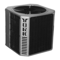
Procedures for inspecting the unit for damage incurred during shipping and transit.

Installation Site and Requirements

Installation Limitations

Adherence to national, state, and local safety codes is mandatory.

Unit Location and Placement

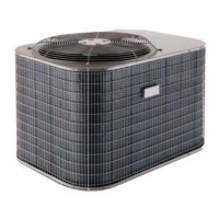
Guidelines for selecting outdoor unit placement considering noise, accessibility, roof/ground level.

Rigging and Handling

Safe techniques for lifting and moving the unit to prevent damage.

Unit Handling, Components, and Wiring

Rigging, Clearances, and Components

Safe rigging, unit clearances, compressor details, and crankcase heater function.

Power and Control Wiring

Instructions for electrical connections, including power supply and control circuits.

Electrical Specifications and Piping

Electrical Data

Table of electrical specifications including voltage, current, and fuse sizes.

Control Wire Sizing

Guidelines for selecting appropriate control wiring gauge to ensure proper voltage.

Refrigerant Piping General Guidelines

Best practices for ensuring an internally clean and dry refrigerant system.

Unit Dimensions

Dimensional Specifications

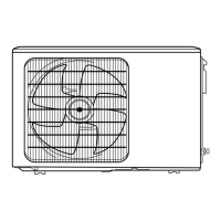
Visual representation and specific measurements for unit dimensions and clearances.

Refrigerant Line Sizing and Flow

Refrigerant Line Sizing

Factors and tables for correctly sizing liquid and vapor refrigerant lines.

Liquid Line Considerations

Guidelines on liquid line pressure drop, vertical rise, and preventing refrigerant flashing.

Vapor Line Considerations

Advice on vapor line sizing for oil return and friction loss, including trap requirements.

Service Valves and Refrigerant Charge

Service Valve Operation

Information on the function and operation of the unit's service valves for maintenance.

Extending Service Ports

Step-by-step instructions for extending service ports for easier access during service.

Refrigerant Line Charge

Table detailing the amount of refrigerant charge per foot for liquid and vapor lines.

Refrigerant Line Installation and System Charging

Refrigerant Line Installation

Detailed steps for connecting refrigerant lines, including brazing and nitrogen purging.

Evacuating and Charging

Procedures for evacuating the system to 500 microns and charging refrigerant.

Alternate Charging Methods

Alternative methods for charging refrigerant based on ambient temperature conditions.

Balance Point Setting

Balance Point Determination

Factors influencing the balance point and references for calculation.

Refrigerant Flow Diagram

Refrigerant Flow Explanation

Diagram illustrating refrigerant flow during cooling and heating cycles.

Charging Curves

EFB090 Charging Curve

Graph showing suction and discharge pressure relationships for EFB090 model.

EFB120 Charging Curve

Graph showing suction and discharge pressure relationships for EFB120 model.

System Operation Modes

Cooling Operation

Detailed sequence of operations for the cooling mode, including safety lockouts.

Heating Operation

Detailed sequence of operations for the heating mode, including safety lockouts.

Special Operating Conditions

Defrost Cycle Operation

Explanation of how and when the defrost cycle is initiated and terminated.

Operation Below 0°F

Specific operational considerations and safety features for sub-zero outdoor temperatures.

Emergency Heat Operation

How the system operates when switched to the emergency heat mode.

Start-Up, Maintenance, and Safety

Pre-Start Checks and Initial Start-Up

Comprehensive pre-start checks and step-by-step initial start-up procedures.

Crankcase Heater and Safety Features

Crankcase heater requirement and overview of built-in safety protections.

Maintenance and Troubleshooting

Advice on cleaning, lubrication, parts, and basic owner troubleshooting.

Related product manuals