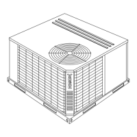
FIG. 4
- UNIT DIMENSIONS AND CLEARANCES
CLEARANCES
Overhead (Top)
1
120"
Front
(Piping and Access Panels)
30"
Left Side 24"
Right Side 24"
Rear 24"
Bottom
2
0"
1Units must be installed outdoors. Overhanging structures
or
shrubs should not obstruct condenser air discharge.
2
Adequate snow clearance must be provided if winter
FRO N T
16
39 - 7/8
BACK
(COIL END)
APPROXIM ATE
CENTER OF GRAVITY
32
76 - 7/8
AIR
OUT
AIR
OUT
AIR
IN
O
O
O
5-3/4
44-9/32
FAN M O TO R
ACCESS
FAN MOTOR ACCESS
EXTERNAL PRESSURE
G AUG E FITTIN G S
CONTROL BOX
ACCESS
9-1/32
76-7/8
7-1/32
39 - 7/8
13-1/4
30-3/4
24-1/2
12-1/8
C
D
F
E
F
E
F
A
B
All dimensions are in inches. They are sub-
ject to change without notice. Certified di-
mensions will be provided upon request.
D
B
C
A
FIG. 5
- POINT LOADS
UNIT
4 - POINT LOAD (LBS)
TOTAL A B C D
180
240
930
990
325
346
218
232
155
165
232
247
Connection
Entry
Connection Size
15 Ton 20 Ton
Suction Line A 1-5/8 ID 2-1/8 ID
Liquid Line B 5/8 OD 5/8 OD
Power Wiring C 2-1/8 KO 2-1/8KO
Control Wiring D 7/8 KO 7/8 KO
Accessory Wiring E 7/8 KO 7/8 KO
Accessory Wiring F 1-3/8 KO 1-3/8 KO
NOTE: Suction line connection is a belled
fitting.
550.23-N6Y
6 Unitary Products Group
 Loading...