14 YORK INTERNATIONAL
MODEL WEIGHT
LOAD VMC LOAD VMC LOAD VMC LOAD VMC VMC
YEA
COND. POINT ISOLATOR POINT ISOLATOR POINT ISOLATOR POINT ISOLATOR ISOLATOR
SHIPPINGOPERATING A B C D PART NO.
Z88DR6
Cu/AI 7,950 8,300 2194 CP-2-31 1911 CP-2-31 2202 CP-2-31 1982 CP-2-31 402237-29
Cu/Cu 9,000 9,350 2457 CP-2-32 2173 CP-2-31 2465 CP-2-32 2244 CP-2-32 402224-2
J44DR7
Cu/AI 9,050 9,400 2602 CP-2-32 2318 CP-2-32 2341 CP-2-32 2121 CP-2-31 402224-2
Cu/Cu 10,100 10,450 2864 CP-4-27 2581 CP-4-27 2604 CP-4-27 2383 CP-4-27 402234-8
J44DR6
Cu/AI 9,050 9,400 2606 CP-2-32 2322 CP-2-32 2345 CP-2-32 2125 CP-2-31 402224-2
Cu/Cu 10,100 10,450 2868 CP-4-27 2585 CP-4-27 2608 CP-4-27 2387 CP-4-27 402234-8
J55DR7
Cu/AI 9,250 9,600 2669 CP-4-27 2385 CP-4-26 2372 CP-4-26 2151 CP-4-26 402234-10
Cu/Cu 10,300 10,650 2931 CP-4-27 2648 CP-4-27 2634 CP-4-27 2414 CP-4-27 402234-8
J44HT6
Cu/AI 9,600 10,050 2690 CP-4-27 2406 CP-4-27 2569 CP-4-27 2349 CP-4-27 402234-8
Cu/Cu 11,000 11,400 3032 CP-4-27 2749 CP-4-27 2911 CP-4-27 2691 CP-4-27 402234-8
J55HT7
Cu/AI 9,800 10,200 2754 CP-4-27 2470 CP-4-27 2586 CP-4-27 2365 CP-4-27 402234-8
Cu/Cu 11,150 11,550 3095 CP-4-28 2812 CP-4-27 2927 CP-4-27 2707 CP-4-27 402237-22
J54ES6
Cu/AI 9,250 9,600 2681 CP-4-27 2371 CP-4-26 2365 CP-4-26 2136 CP-4-26 402234-10
Cu/Cu 10,450 10,800 3005 CP-4-27 2696 CP-4-27 2653 CP-4-27 2424 CP-4-27 402234-8
J65ES7
Cu/AI 9,500 9,800 2771 CP-4-27 2444 CP-4-27 2403 CP-4-27 2167 CP-4-27 402234-8
Cu/Cu 10,700 11,050 3096 CP-4-28 2768 CP-4-27 2691 CP-4-27 2454 CP-4-27 402237-22
J55HT8
Cu/AI 9,900 10,350 2798 CP-4-27 2494 CP-4-27 2625 CP-4-27 2389 CP-4-27 402234-8
Cu/Cu 11,250 11,700 3139 CP-4-28 2835 CP-4-27 2966 CP-4-27 2730 CP-4-27 402237-22
J66HT9
CU/AI 10,300 10,750 2930 CP-4-27 2626 CP-4-27 2697 CP-4-27 2461 CP-4-27 402234-8
Cu/Cu 11,700 12,100 3272 CP-4-28 2967 CP-4-27 3039 CP-4-27 2802 CP-4-27 402237-22
J65HT8
Cu/AI 10,050 10,450 2871 CP-4-27 2521 CP-4-27 2649 CP-4-27 2398 CP-4-27 402234-8
Cu/Cu 11,400 11,850 3212 CP-4-28 2862 CP-4-27 2990 CP-4-27 2739 CP-4-27 402237-22
J76HT9
Cu/AI 10,400 10,800 2990 CP-4-27 2648 CP-4-27 2709 CP-4-27 2459 CP-4-27 402234-8
Cu/Cu 11,750 12,200 3331 CP-4-28 2984 CP-4-27 3050 CP-4-27 2800 CP-4-27 402237-22
J66MT8
Cu/AI 11,300 11,900 3008 CP-4-27 2703 CP-4-27 3200 CP-4-28 2964 CP-4-27 402237-22
Cu/Cu 12,650 13,250 3349 CP-4-28 3045 CP-4-28 3541 CP-4-28 3305 CP-4-28 402237-20
J77MT9
Cu/AI 11,650 12,250 3127 CP-4-28 2822 CP-4-27 3261 CP-4-28 3024 CP-4-27 402237-41
Cu/Cu 13,000 13,600 3468 CP-4-28 3163 CP-4-28 3602 CP-4-28 3366 CP-4-28 402237-20
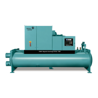
Ground Level Locations
It is important that the units be installed on a substantial
base that will not settle. A one piece concrete slab with
footers extended below the frost line is highly recom-
mended. Additionally, the slab should not be tied to the
main building foundations as noise and vibration may be
transmitted.
Mounting holes are provided in the steel channel for bolt-
ing the unit to its foundation. (See DIMENSIONS).
For ground level installations, precautions should be taken
to protect the unit from tampering by or injury to unau-
thorized persons. Screws and/or latches on access pan-
els will prevent casual tampering. However, further safety
precautions such as a fenced-in enclosure or locking
devices on the panels may be advisable. A tamperproof
kit is available as an option. Check local authorities for
safety regulations.
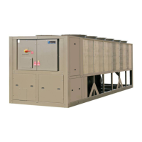
Rooftop Locations
Choose a spot with adequate structural strength to safely
support the entire weight of the unit and service person-
nel. Care must be taken not to damage the roof. Consult
the building contractor or architect if the roof is bonded.
Roof installations should have wooden beams (treated
to reduce deterioration), cork, rubber or vibration isola-
tors under the base to minimize vibration.
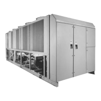
SHIPPING BRACES
Two shipping brackets (typically galvanized steel) which
run diagonally along each side of the unit, must be re-
moved once the unit is mounted on its foundation. A
third bracket on the right rear of the unit should also be
removed. This bracket runs across the bottom right cor-
ner of the unit behind the compressors.
SPRING ISOLATORS (OPTIONAL)
When ordered (four) 4 spring isolators will be furnished.
1. Identify isolator and locate at proper mounting point
using table below.
2. Block up equipment so as to install spring mounts
with pin on top of housing into Equipment Mounting
Holes.
3. Mounting Adjust Nut is inside the isolator mount lo-
cated just below the top plate of the mount. Turn nut
2 turns clockwise (down) to load spring mount at each
location.
4. Take two additional turns on Adjustment Nut of each
location.
5. Repeat step No. 3 as many times as necessary to
bring height of isolator to proper height.
6. Take additional turns on mounts at low side or corner
to level the equipment.
 Loading...