CONTROL WIRING DIAGRAMS General
YHMY range – electrical connections
Terminal arrangement
Electrical connections with York wall-mounted controls
• Manual switchover of the 3 fan speeds
• Manual switchover of the season cycle (SUM-WINT)
• Fan thermostation (ON-OFF)
• Water valve thermostation(ON-OFF) (continual ventilation)
• Possibility of applying the minimum TME sensor
• Possibility of controlling season cycle switchover (SUM-
WINT) either through a remote electric phase signal (cen-
tral) or in the automatic mode with a built-in CHANGEO-
VER switch in contact with the water pipework (two-pipe
system); for this set-up the jumper on the control board
must be re-positioned (see instruction sheet accompany-
ing the control).
• Identical features to the TR, but with the addition of:
• Manual switchover of the 3 fan speeds
• Fan thermostation (ON-OFF)
• Water valve thermostation (ON-OFF)
• Thermostation(ON-OFF) on the valves and motor simul-
taneously
• Automatic Summer/Winter changeover through a remo-te
electric phase signal (central) or in the automatic mode
with a built-in CHANGEOVER switch in contact with the
water pipework (two-pipe system).
Identification Code
TR 9060541
Identification Code
ATR 9060542
Minimum speed
Medium speed
Maximum speed
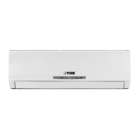
YHMY
N245
20°°C
42N5
MC3MC2MC1
213456217 218
L
N
PE
CH
E
CH
PE
N
L
8 12712 6543 12
MC1 MC2 MC3
25N4
TR without valves TR with 1 valve
YHMYYHMY
TR TR
42N5
MC3MC2MC1
213456 2211
L
N
PE
CH
E
CH
PE
N
L
1212 6543 12
MC1 MC2 MC3
5N24
ATR without valves ATR with 1 valve
YHMY YHMY
ATR ATR
20°°C
GB
7
 Loading...