JOHNSON CONTROLS
7
FORM 160.84-N1
ISSUE DATE: 11/22/2016
LIST OF FIGURES
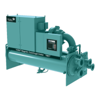
FIGURE 1 - YMC
2
Chiller Components .....................................................................................................................9
FIGURE 2 - Form 1 and 2 Rigging with Side Spreader Bar ....................................................................................16
FIGURE 3 - Form 1 and 2 Rigging without Side Spreader Bar ...............................................................................16
FIGURE 4 - Driveline Rigging..................................................................................................................................18
FIGURE 5 - Form 3 Rigging without Side Spreader Bars .......................................................................................19
FIGURE 6 - Variable Speed Drive Rigging ..............................................................................................................19
FIGURE 7 - Power Panel ........................................................................................................................................20
FIGURE 8 - OptiView Control Center ......................................................................................................................20
FIGURE 9 - Form 7 Rigging with Side Spreader Bars ............................................................................................21
FIGURE 10 - Driveline Rigging................................................................................................................................22
FIGURE 11 - Variable Speed Drive Rigging ............................................................................................................ 23
FIGURE 12 - Power Panel ......................................................................................................................................23
FIGURE 13 - OptiView Control Center ....................................................................................................................24
FIGURE 14 - Form 9 and 10 Rigging with Side Spreader Bars ..............................................................................24
FIGURE 15 - Form 9 and 10 Rigging without Side Spreader Bars .........................................................................25
FIGURE 16 - Variable Speed Drive Rigging ............................................................................................................26
FIGURE 17 - Variable Speed Drive Rigging ............................................................................................................27
FIGURE 18 - Form 11 Condenser Assembly Rigging with Side Spreader Bars ...................................................... 28
FIGURE 19 - Form 11 Evaporator Assembly Rigging with Side Spreader Bars ...................................................... 28
FIGURE 20 - OptiView Control Center ....................................................................................................................29
FIGURE 21 - Neoprene Isolators ............................................................................................................................32
FIGURE 22 - Skid Options ......................................................................................................................................33
FIGURE 23 - Spring Isolators .................................................................................................................................34
FIGURE 24 - Pressure Relief Piping .......................................................................................................................35
FIGURE 25 - Schematic of a Typical Piping Arrangement ...................................................................................... 36
FIGURE 26 - Typical Refrigerant Vent Piping ..........................................................................................................38
FIGURE 27 - Unit Insulation .................................................................................................................................... 40
FIGURE 28 - Shell Reassembly .............................................................................................................................. 41
FIGURE 29 - YMC
2
Piping Reassembly Hardware Identication ............................................................................43
FIGURE 30 - YMC
2
Form 3 Reassembly Hardware Identication ...........................................................................44
FIGURE 31 - YMC
2
Form 7 Reassembly Hardware Identication ...........................................................................45
FIGURE 32 - VSD Mounting Hardware Identication ..............................................................................................46
FIGURE 33 - Power and Control Panel Mounting Hardware Identication .............................................................47
FIGURE 34 - YMC
2
Form 9 and Form 10 Reassembly Hardware Identication .....................................................49
FIGURE 35 - Shell Reassembly .............................................................................................................................. 50
FIGURE 36 - Refrigerant Piping .............................................................................................................................. 50
FIGURE 37 - YMC
2
Form 11 Reassembly Hardware Identication ......................................................................... 51
FIGURE 38 - Adjustable End Fitting ........................................................................................................................ 52
FIGURE 39 - Back off Locknut ................................................................................................................................52
FIGURE 40 - Screw Fitting into Port........................................................................................................................52
FIGURE 41 - Torque Fitting .....................................................................................................................................53
FIGURE 42 - SAE or ISO 6149 Straight Thread O-ring Port ................................................................................... 53
FIGURE 43 - Dimensions - 197 & 246 Compressor Units Ft-In (Mm) .....................................................................56
FIGURE 44 - Evaporator - Compact Water Boxes (1-Pass Nozzle Arrangements) ...............................................59
FIGURE 45 - Evaporator - Compact Water Boxes (2-Pass Nozzle Arrangements) ...............................................59
FIGURE 46 - Evaporator - Compact Water Boxes (3-Pass Nozzle Arrangements) ...............................................59
FIGURE 47 - Evaporator And Condenser - 150 & 300 Psi Compact Water Boxes ................................................. 61
FIGURE 48 - Condenser - Compact Water Boxes (1-Pass Nozzle Arrangements) ...............................................63
FIGURE 49 - Condenser - Compact Water Boxes (3-Pass Nozzle Arrangements) ...............................................63
FIGURE 50 - Condenser - Compact Water Boxes (2-Pass Nozzle Arrangements) ...............................................63
FIGURE 51 - Evaporator - Marine Water Boxes (1-Pass Nozzle Arrangements) ..................................................64

 Loading...