251934-YTG-G-0708
Johnson Controls Unitary Products 99
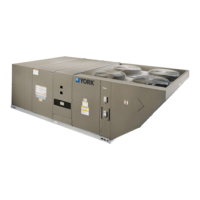
ZF Unit Dimensions Front View
NOTE: All entry holes should be field sealed to prevent rain water
entry into the building.
RET URN
A I R
SUP P L Y
A I R
BOT T OM S UP P L Y
A ND R ET URN
A IR O P ENINGS
(See N ote)
(B)
P OWER W IRING
ENT RY
(A )
CONT ROL W IRING
ENT RY
NOT E:
For c urb m ounted u nits, r efer to th e c urb h anger
dimensions o f th e c urb fo r th e p roper s ize o f th e
supply a nd r eturn a ir d uct c onnections.
UNIT B A SE W IT H R A I L S
Shown s eparately to i llustrate
Bottom D uct o penings, P ower
and G as P iping C onnection
locations
12-1/2"
9-1/4"
8-1/8"
9-3/4"
3-3/4"
(B)
P OWER W IRING
ENT RY
(A )
CONT ROL W IRING
ENT RY
CONDENSER
COIL S
OP T IONA L C OIL
GUA RD K IT
COMP RESSOR
A CCE SS
(See d etail " X")
ECONOMIZER / M OT ORIZED D A M P ER,
FIXED O UT DOOR IN T A KE A IR A ND
P OWER E XHA UST R A IN H OODS
(See d etail " Y ")
FIELD-SUPPLIED
DISCONNECT SWITCH
LOCATION
BLOWER
COMPARTMENT
ACCESS
(Auxiliary)
DOT P L UG
(For p ressure
Drop R eading)
FRONT
VIEW
CONT ROL B OX
A CCE SS
21"
5"
9-3/4"
11-1/2"
2-3/4" 21-1/2"
33"
35"
5-7/8"
46-5/8"
7-1/8"
6-3/8"
VENT A IR
OUT L ET
HOODS
COMBUST ION
A IR IN L ET
HOOD
GA S H EA T
A CCE SS
(C)
GA S S UP P L Y
ENT RY
46-5/8"
11-1/8"
(D)
GA S S UP P L Y
ENT RY
RET URN A IR
SUP P L Y A IR
OUT DOOR A IR
OUT DOOR A IR
(Economizer)
92"
24-1/4" (15 Ton)
35-1/4" (17.5
thru 25 Ton)
125-1/4" (15
T
on)
136-1/4" (17.5
thru 25 Ton)
48-5/8" (15 Ton)
52-5/8" (17.5 thru 25 Ton)
ELECTRIC
BLOWER ACCESS
(Location Of
Optional VFD)
BLOWER MOTOR ACCESS
(Location Of Optional
VFD Bypass)
All dimensions are in inches. They are
subject to change without notice. Certi-
fied dimensions will be provided upon
request.
Utilities Entry
Hole
Opening Size
Diameter
Used For
A
1-1/8” KO
Control Wiring
Front
3/4” NPS (Fem.) Bottom
B
3-5/8” KO
Power Wiring
Front
3” NPS (Fem.) Bottom
C 2-3/8” KO Gas Piping (Front)
1
D 1-11/16” Hole Gas Piping (Bottom)
1,2
1. One-inch Gas Piping NPT Required.
2. Opening in the bottom to the unit can be located by the slice in the
insulation.
 Loading...