Do you have a question about the Yuanxin Electric YX2000 and is the answer not in the manual?
Key notes about product illustrations, company commitment to improvement, and contact information.
Guidelines and warnings for safe installation, wiring, and operation phases.
Important precautions for motor insulation, thermal protection, and operating conditions.
Lists available YX3000 series inverter models, voltage levels, and power ranges.
Covers input, output, control functions, environment, and structural specifications of the inverter.
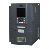
Identifies and illustrates the main physical components and connection points of the inverter.
Provides detailed physical dimensions of the inverters across different power ranges with diagrams.
Lists optional accessories like remote control panels, communication cables, and adaptors.
Covers environmental requirements and mounting space/direction for inverter installation.
Instructions for removing/mounting the front cover and essential wire connection warnings.
Details the main circuit wiring diagram and terminal descriptions for AC power input and motor output.
Provides a comprehensive wiring diagram illustrating all connections for the inverter.
Explains the layout and functions of control circuit terminals and jumpers.
Illustrates wiring procedures for analog voltage and current input/output signals.
Details wiring for RS485 communication ports for connecting to upper computers or networks.
Provides guidelines for EMC installation to minimize electromagnetic interference.
Offers best practices for wiring connections and grounding to ensure EMC compliance.
Explains running command channels, frequency settings, and inverter running states.
Outlines the five prioritized running modes: JOG, Close Loop, PLC, Multi-stage, and Normal.
Introduces how to operate and utilize the inverter's control panel for various functions.
Details the functions assigned to each key and the analog potentiometer on the control panel.
Explains the LED display, unit indicators, and state indicators on the control panel.
Describes how parameters and states are displayed on the control panel in different modes (stopping, running, alarm).
Covers various operations performed via the control panel, such as switching monitoring parameters and setting codes.
Explains the symbols used in the parameter tables, indicating modify status.
Lists and defines function code parameters across various groups (P0-P9, PA, PF).
Lists state monitoring parameters (B-Monitoring) for output frequency, voltage, current, etc.
Explains basic running parameters like control mode and frequency channel selection.
Details parameters for setting frequency using analog inputs (VI, CI) and pulse inputs.
Defines parameters for controlling the inverter's start and braking functions.
Covers parameters for frequency control channel combination, parameter initialization, and auto energy saving.
Explains how to configure input terminals (X1-X8) for various functions like multi-stage speed control.
Details motor overload protection, overvoltage stall, current limit, and restart settings.
Explains parameters for recording and retrieving fault codes and related data.
Covers parameters for PID control, pressure limits, and hibernation modes.
Defines parameters for PLC running modes, stage settings, and timing.
Details parameters for configuring swing frequency operations in applications like textile winding.
Covers parameters for motor auto-tuning, rated values, and vector control adjustments.
Mentions factory function parameters that users should not amend.
Lists common fault codes, possible reasons, and troubleshooting steps for inverter issues.
Explains how to search for recorded fault codes and running parameters.
Provides methods for resetting the inverter after a fault occurs.
Discusses potential hazards and the importance of daily and periodic inspections for inverter longevity.
Lists essential checks to perform before starting the inverter daily.
Details periodic inspection items and troubleshooting for control terminals, heat sinks, and components.
Recommends thermal maintenance and lists the replacement intervals for key inverter components.
Outlines the company's warranty conditions and service charges for repairs.
Introduces the RS485 communication interface and MODBUS protocol for inverter networking and monitoring.
Illustrates networking methods for inverters as slaves and for multi-machine interaction.
Explains communication modes (master/slave) and protocols used in the RS485 network.
Details the character structure and data formats for the ASCII communication protocol.
| Brand | Yuanxin Electric |
|---|---|
| Model | YX2000 |
| Category | Controller |
| Language | English |