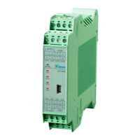
Wiring diagram of AI-70482 multi-channel
temperature controller
Wiring diagram and explanation of indicating lights of D5 panel
MODE: Status of communication and alarm
OP1~OP4: Output of channel 1~4.
Terminal 1~2: Power 100~240VAC or 24VAC/DC
Terminal 9~12: Positive poles of 4 thermocouple inputs
Terminal 15~16: Negative poles of 4 thermocouple inputs in common.
Terminal 5~8: Positive poles of 4 SSR voltage outputs
Terminal 3~4: Negative poles of 4 SSR voltage outputs in common. The
specification of SSR outputs is 12~16VDC/20mA with short-circuit
protection.
Terminal 13~14: RS485 communication.
No alarm output is available in this D5 panel.
This wiring diagram is valid for panel size code A, C, E, E5
or etc.
For instruments with dimension B and F, the diagram is
clock-wisely rotated by 90°. The terminal numbers keep
unchanged.
 Loading...