Do you have a question about the YUNEEC Typhoon G and is the answer not in the manual?
This guide is not a substitute for the full instruction manual.
SD card contains tutorial video, electronic manual, and showcases.
Charge using 100-240V AC outlet or 12V DC accessory socket.
Green blinking LED indicates power, red blinking indicates charging.
Fully discharged battery takes approximately 2 hours to charge.
Follow all instructions to prevent property damage and injury from mishandling.
Install corresponding A and B propellers securely, using the included tool.
Do not over-tighten the propellers when using the tool.
Insert the battery until the door closes properly to engage the connector.
Plug audio connector into audio port and 4PIN power connector into GB203.
Plug the MINI USB connector into the USB interface of the GoPro Camera.
Operate in open areas (10000 sq ft/930 sqm) free from people, vehicles, trees, obstructions.
Never fly near or above crowds, airports, or buildings.
Ensure minimum 100° clearance from tall buildings/obstructions for clear sky view.
Place TYPHOON on a level and stable surface before powering on.
Insert GoPro camera into GB203 frame and secure with retaining screw.
Do not over-tighten the retaining screw for the GoPro camera.
Ensure a takeoff zone of 10000 sq ft (930 sqm) is clear.
Step back approximately 26 feet (8 meters) behind TYPHOON for pilot location.
Turn on ST10+ controller first, then TYPHOON aircraft.
Turn off TYPHOON aircraft first, then ST10+ controller.
Do not touch or move TYPHOON until initialization is complete.
Solid green (Smart Mode) or purple (Angle/Pilot Mode) indicates GPS lock.
Blinks green slowly when initialization is completed.
MK58 supplied with power, blue LED is on.
Set video mode for GoPro camera before starting motors.
MK58 enables real-time image transmission with GB203.
GoPro App can achieve real-time transmission without MK58 when using SteadyGrip.
GoPro Wi-Fi can interfere with quadcopter receiver, causing signal loss or crash.
Turn off GoPro Wi-Fi before powering on the quadcopter to prevent crashes.
Tap 'Flight Setting' on ST10+ to begin binding the MK58.
Select 'Camera Select', then 'GoPro', tap 'Select' and 'OK'.
Tap 'Bind' and input password '12345678' to complete binding.
MK58 red LED blinks, real-time images shown on ST10+ interface.
Press and hold red START/STOP button for 3 seconds to start motors.
Press and hold red START/STOP button for 2 seconds to stop motors.
Ensure motors are stopped before moving TYPHOON after starting.
Slowly raise left-hand stick to take off and climb; return stick to center at desired altitude.
Learn TYPHOON response in Smart Mode (follows pilot) and Angle Mode (controls relative to nose).
Left stick controls altitude: raise to climb, lower to descend, center to maintain.
Release control sticks to self-level and hold position with GPS lock.
Activate Home Mode for automatic return and landing within 13-26 ft (4-8m).
Slowly lower left stick to land, or activate Home Mode for automatic landing.
Land immediately on first low voltage warning; land if battery voltage drops below 10.7V.
Turn off TYPHOON before ST10+, remove battery, and allow to cool before recharging.
Set climb/descend and directional rates using turtle (low) or rabbit (high) positions.
Use the switch above the right-hand control stick to select Smart, Angle, or Home Mode.
TYPHOON moves relative to pilot; best for beginners, features Follow Me.
TYPHOON follows pilot by adjusting location to ST10+ GPS signal.
Aircraft maintains constant altitude and cannot detect obstacles in Follow Me mode.
Camera tracks remote controller, automatically tilting its angle.
Press button to switch between Watch Me (Green) and Follow Me (Orange).
Keeps TYPHOON approximately 26 feet (8 meters) from the pilot.
Geo-fence limits TYPHOON travel to 300 feet (91 meters); default limit recommended.
Smart Mode requires GPS signal; loss switches to Angle Mode.
Loss of GPS signal can cause crash or 'fly away' if Angle Mode control is lost.
Follow Me feature is disabled if ST10+ has less than 6 satellites.
Aircraft moves relative to control stick input, regardless of nose direction.
Push right stick left to bank left; push right to bank right, relative to aircraft nose.
TYPHOON holds position and maintains level attitude when sticks are centered.
Improper control in Angle Mode can lead to crash or 'fly away'.
TYPHOON flies back to pilot's current location and lands automatically.
Lands within 13-26 ft (4-8m) of the pilot's location.
Flies back at current altitude if >33ft, or climbs to 33ft if <33ft before returning.
Switch to Smart/Angle Mode to avoid obstacles during Return to Home.
Home Mode requires GPS signal; loss switches to Angle Mode.
Use the slider (A) on the ST10+ to set the pitch/tilt position (B) of the GB203.
Shows aircraft flight mode, GPS status, Watch Me/Follow Me button, and flight settings.
Never attempt to fly via First-Person View (FPV) due to crash risk.
Double tap the center of the screen to increase the size of the video viewing area.
Information may change due to software updates; check official website for latest documents.
Full manual, calibration sheet, LED status, GUI, firmware, and tutorial videos available online.
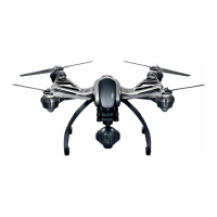
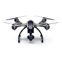
GB203 gimbal, LED status indicators, power switch, MK58, and USB port.
Control sticks, buttons, display, antennas, volume/navigation buttons, and SD card slot.
Details functions of Rudder/Yaw, Throttle/Altitude, Elevator/Pitch, and Aileron/Roll controls.
Identifies Start/Stop Motors, Flight Mode Selection, and other controller buttons.
| Max Flight Time | 25 minutes |
|---|---|
| Camera | CGO3 |
| GPS | Yes |
| Battery Voltage | 11.1 V |
| Battery Configuration | 3S |
| Max Ascent Rate | 5 m/s |
| Max Descent Rate | 3 m/s |
| Radio System | 2.4 GHz |
| Video Transmission Range | 500 m |
| Gimbal | 3-axis |
| Max Range | 1 km |
| Battery | 5400 mAh |
| Flight Modes | Smart Mode, Angle Mode, Home Mode |
| Max Speed | 18 m/s |
| Operating Temperature Range | -10°C to 40°C |
| Camera Resolution | 12 MP |
| Video Resolution | 4K |
| Charging Time | 2 hours |