Do you have a question about the Yuyao gongyi XMT-808 series and is the answer not in the manual?
| Brand | Yuyao gongyi |
|---|---|
| Model | XMT-808 series |
| Category | Temperature Controller |
| Language | English |
Indicates procedures that may lead to severe injury or death if not followed.
Highlights content requiring special attention or important information.
Defines supported input types (Thermocouple, RTD, Voltage, Current) and measurement ranges.
Details accuracy, reaction time, and available control methods like ON/OFF and PID.
Covers output types, communication protocols (RS485), and alarm functions.
Outlines electrical tolerance, manual mode, and available power options.
Explains the meaning of each segment in the product model code.
Provides the wiring diagram for the XMT-808 model.
Wiring diagram specific to the XMTD-808 model.
Wiring diagram applicable to XMTA, E, and F models.
Wiring diagram specific to the XMTG-808 model.
Illustrates connection methods for controllable silicon outputs.
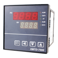
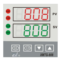
Diagram showing the layout of the controller's front panel.
Detailed explanation of each button, LED, and display element.
How to set the target temperature (setpoint) for the controller.
Guide to modifying parameters and switching control modes.
Explanation of auto-tuning functions and manual operation methods.
Visual guide to the controller's operational logic and parameter flow.
Detailed explanation of each parameter's meaning, range, and usage.
Details on configuring linear current output specifications and ranges.
Explanation of how time proportion output control operates.
Setup method for integrating long-distance transfer pressure gauges.
Methods for accurately compensating thermocouple cold junction temperatures.
Details ON/OFF control and alarm setup procedures.
Setting the instrument to function as a temperature transmitter for signal output.
Information on setting up communication interfaces and connections.
Table listing common faults, their causes, and recommended solutions.
Initial setup and checking steps for the controller.
Details on maintenance period, fees, and the process for product repair.